SECTION 3 - CHASSIS & TURNTABLE
3-214
3121160
Lubrication Guide
IT IS IMPORTANT THAT THE COMPRESSOR OIL BE OF A RECOMMENDED TYPE
AND THAT IT IS INSPECTED AND REPLACED TOGETHER WITH THE OIL AND AIR
FILTERS, IN ACCORDANCE WITH THIS MANUAL.
The result of poorly maintained lubricant and/or filters may
produce hazardous conditions resulting in ignition, which
could cause a fire in the sump. Damage to equipment and seri-
ous bodily harm may result.
It is not possible to establish limits on all physical and chemical
properties of lubricants which can affect their performance
over a broad range of operating and environmental influ-
ences. The responsibility for recommending a suitable lubri-
cant must rest with the user’s lubricant supplier and their
knowledge of the suitability of their lubricants in screw com-
pressors, operating in the particular environment involved.
TYPES OF LUBRICANT TO BE CONSIDERED:
NOTE:
Factory Fill - A.T.F.
–
Dexron® III or equivalent.
DO NOT MIX OILS OF DIFFERENT TYPES.
1.
Automatic Transmission Fluids (i.e., Dexron® III):
Are
suitable for the majority of applications. They are com-
monly applied in heavy duty, high temperature condi-
tions and also where temperatures are consistently
below freezing (32°F [0°C]), down to approximately 0°F
(-18°C).
In light load and/or high humidity operating conditions
A.T.F. can absorb moisture and may result in emulsifica-
tion of the lubricant. If this occurs change lubricant
immediately since the lubricating properties are break-
ing down. If this condition persists, consider changing to
a different type of lubricant (consult supplier).
2.
Industrial Type Oils:
Should be of premium quality
non-detergent mineral oil, viscosity grade SAE20 ISO
68). Industrial oils may be better for high humidity and/
or low load factor, where condensed moisture and
emulsification may occur. Water will separate and must
be drained from the oil sump (daily if necessary In addi-
tion to the primary oil characteristics, good water sepa-
ration is required.
These lubricants should be applied where conditions
above 32°F (0°C) prevail.
3.
Synthetic Lubricants:
In so far as know, all the elasto-
meric components and metals used in the compressor
are fully compatible with Synthetic Hydrocarbon (SHC)
and Diester Lubricants. However, the synthetic lubricant
should not employ Viscosity Index Additives since, they
could precipitate out and cause plugging. Viscosity
ranges selected should be based on those outlined in
Prime Characteristics and in close liaison with the lubri-
cant supplier.
VARIOUS FACTORS CAN AFFECT ”EXTENDED LIFE” LUBRICANTS, SUCH AS
REACTIVE GASES OR VAPORS WHICH COULD BE INGESTED INTO THE COM-
PRESSOR AND MAY ADVERSELY AFFECT THESE LUBRICANTS. IT IS RECOM-
MENDED WITH THESE LUBRICANTS TO MAINTAIN OIL FILTER CHANGES AT
RECOMMENDED INTERVALS AND PARTICIPATE IN AN OIL SAMPLING PRO-
GRAM WITH THE LUBRICANT SUPPLIER.
Oil Filter Replacement
The compressor oil filter is a spin on, throw away type. Before
attempting to remove the oil filter, ensure all air is relieved
from the system.
USE ONLY ORIGINAL EQUIPMENT FILTERS, OTHER FILTERS MAY NOT HAVE
CORRECT PRESSURE RATING OR EVEN DIFFERENT THREAD.
REMOVAL:
1.
Remove old filter (use strap wrench if required) by turn-
ing Anti-Clockwise and discard as appropriate and in
accordance with any pertinent regulations
2.
Clean filter head with lint free wiper or cloth.
REPLACEMENT:
1.
Apply a light film of oil to the seal surface on the new
element.
2.
Screw new element on, clockwise by hand until seal
contacts filter head, then turn an additional 3/4 turn (by
hand).
3.
Run compressor and test for leaks.
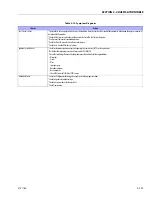
Table 3-17. Prime Lubricant Characteristics
Viscosity
160 - 210 SUS at 100°F (38°C)
47 SUS or greater at 210°F (99°C)
Flashpoint
400°F (204°C) minimum
Pour point
Must be at least 20°F (-7°C) lower than the lowest expected
ambient operating temperature
Contain
Rust and Oxidation Inhibitors
Contain
Foam Suppressors
Summary of Contents for 740AJ
Page 2: ......
Page 55: ...SECTION 3 CHASSIS TURNTABLE 3121160 3 3 This page left blank intentionally...
Page 116: ...SECTION 3 CHASSIS TURNTABLE 3 64 3121160 Figure 3 44 Swing Hub Prior to SN 0300074383...
Page 203: ...SECTION 3 CHASSIS TURNTABLE 3121160 3 151 Figure 3 77 EFI Component Location...
Page 206: ...SECTION 3 CHASSIS TURNTABLE 3 154 3121160 Figure 3 78 ECM EPM Identification ECM EPM...
Page 224: ...SECTION 3 CHASSIS TURNTABLE 3 172 3121160 Figure 3 83 Deutz EMR 2 Troubleshooting Flow Chart...
Page 228: ...SECTION 3 CHASSIS TURNTABLE 3 176 3121160 Figure 3 87 EMR 2 Engine Plug Pin Identification...
Page 229: ...SECTION 3 CHASSIS TURNTABLE 3121160 3 177 Figure 3 88 EMR 2 Vehicle Plug Pin Identification...
Page 230: ...SECTION 3 CHASSIS TURNTABLE 3 178 3121160 Figure 3 89 EMR2 Fault Codes Sheet 1 of 5...
Page 231: ...SECTION 3 CHASSIS TURNTABLE 3121160 3 179 Figure 3 90 EMR2 Fault Codes Sheet 2 of 5...
Page 232: ...SECTION 3 CHASSIS TURNTABLE 3 180 3121160 Figure 3 91 EMR2 Fault Codes Sheet 3 of 5...
Page 233: ...SECTION 3 CHASSIS TURNTABLE 3121160 3 181 Figure 3 92 EMR2 Fault Codes Sheet 4 of 5...
Page 234: ...SECTION 3 CHASSIS TURNTABLE 3 182 3121160 Figure 3 93 EMR2 Fault Codes Sheet 5 of 5...
Page 303: ...SECTION 4 BOOM PLATFORM 3121160 4 31 Figure 4 20 Rotator Assembly HELAC...
Page 460: ...SECTION 5 BASIC HYDRAULIC INFORMATION AND SCHEMATICS 5 116 3121160 NOTES...
Page 467: ...SECTION 6 JLG CONTROL SYSTEM 3121160 6 7 Figure 6 2 ADE Block Diagram...
Page 534: ...SECTION 6 JLG CONTROL SYSTEM 6 74 3121160 NOTES...
Page 580: ...SECTION 7 BASIC ELECTRICAL INFORMATION SCHEMATICS 7 46 3121160 NOTES...
Page 581: ......

