SECTION 3 - CHASSIS & TURNTABLE
3-76
– JLG Lift –
3121160
17.
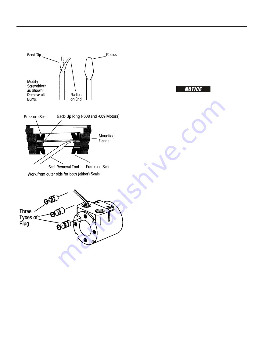
A metal plug, with seal, plugs a machining hole in
the housing. It is not necessary to remove plug and
replace seal unless leakage occurs around plug. To
remove plug, insert 5 mm (0.187 in.) hex key
through port opening and push it out. The 009 plug
is not interchangeable with 007 and 008 plugs.
Inspection and Cleaning
Check all mating surfaces. Replace any parts with
scratches or burrs that could cause leakage or damage.
Clean all metal parts in clean solvent. Blow dry with air. Do
not wipe parts with cloth or paper towel because lint or
other matter could get into the hydraulic system and
cause damage.
Check around key slot and chamfered area of shaft for
burrs, nicks or sharp edges that could damage seals dur-
ing reassembly. Remove nicks or burrs with hard smooth
stone (such as an Arkansas stone). Do not file or grind
motor parts.
NOTE:
Lubricate all seals with petroleum jelly. Use new
seals when reassembling motor.
DO NOT STRETCH SEALS BEFORE INSTALLING THEM.
Cleanliness is extremely important in the successful appli-
cation of Loctite. Before Loctite can be applied, the parts
should be cleaned as follow:
NOTE:
Fully cured Loctite resists most solvents, oils, gaso-
line and kerosene and is not affected by cleaning
operations. It is not necessary to remove cured Loc-
tite that is securely bonded in tapped holes; however,
any loose particles of cured Loctite should be
removed.
a.
Wash the housing with solvent to remove oil,
grease and debris. Pay particular attention to
four tapped holes on flanged end.
b.
Blow dry with compressed air. Clean and dry
tapped holes.
c.
Wire brush screw threads to remove cured Loc-
tite and other debris. Discard any screws that
have damaged threads or rounded heads.
d.
Wash screws with non-petroleum base solvent.
Blow dry with compressed air.
Assembly
SHAFT END
1.
If you remove plug and seal, lubricate seal and
install on plug. Some plugs have two o-ring grooves
but require only one o-ring. Install o-ring in groove
closest to end of plug. Push plug into housing. Be
careful not to damage seal.
Summary of Contents for 740A
Page 1: ...Service and Maintenance Manual Models 740A 740AJ P N 3121160 January 8 2013 ...
Page 2: ......
Page 52: ...SECTION 2 GENERAL 2 12 JLG Lift 3121160 NOTES ...
Page 109: ...SECTION 3 CHASSIS TURNTABLE 3121160 JLG Lift 3 57 Figure 3 39 Swing Hub ...
Page 135: ...SECTION 3 CHASSIS TURNTABLE 3121160 JLG Lift 3 83 Figure 3 48 Rotary Coupling Port Location ...
Page 153: ...SECTION 3 CHASSIS TURNTABLE 3121160 JLG Lift 3 101 Figure 3 54 EFI Component Location ...
Page 156: ...SECTION 3 CHASSIS TURNTABLE 3 104 JLG Lift 3121160 Figure 3 55 ECM EPM Identification ECM EPM ...
Page 173: ...SECTION 3 CHASSIS TURNTABLE 3121160 JLG Lift 3 121 Figure 3 65 EMR2 Fault Codes Sheet 1 of 5 ...
Page 174: ...SECTION 3 CHASSIS TURNTABLE 3 122 JLG Lift 3121160 Figure 3 66 EMR2 Fault Codes Sheet 2 of 5 ...
Page 175: ...SECTION 3 CHASSIS TURNTABLE 3121160 JLG Lift 3 123 Figure 3 67 EMR2 Fault Codes Sheet 3 of 5 ...
Page 176: ...SECTION 3 CHASSIS TURNTABLE 3 124 JLG Lift 3121160 Figure 3 68 EMR2 Fault Codes Sheet 4 of 5 ...
Page 177: ...SECTION 3 CHASSIS TURNTABLE 3121160 JLG Lift 3 125 Figure 3 69 EMR2 Fault Codes Sheet 5 of 5 ...
Page 244: ...SECTION 4 BOOM PLATFORM 4 28 JLG Lift 3121160 Figure 4 14 Rotator Assembly HELAC ...
Page 286: ...SECTION 4 BOOM PLATFORM 4 70 JLG Lift 3121160 NOTES ...
Page 307: ...SECTION 5 HYDRAULICS 3121160 JLG Lift 5 21 Figure 5 17 Variable Displacement Pump Rexroth ...
Page 316: ...SECTION 5 HYDRAULICS 5 30 JLG Lift 3121160 NOTES ...
Page 319: ...SECTION 6 JLG CONTROL SYSTEM 3121160 JLG Lift 6 3 Figure 6 2 ADE Block Diagram ...
Page 328: ...SECTION 6 JLG CONTROL SYSTEM 6 12 JLG Lift 3121160 Figure 6 11 Control Module Location ...
Page 374: ...SECTION 6 JLG CONTROL SYSTEM 6 58 JLG Lift 3121160 NOTES ...
Page 406: ...SECTION 7 BASIC ELECTRICAL INFORMATION SCHEMATICS 7 32 JLG Lift 3121160 NOTES ...
Page 407: ......


