SECTION 3 - CHASSIS & TURNTABLE
3120746
– JLG Lift –
3-27
3.7 DRIVE MOTOR (S/N 85132 TO PRESENT)
Description
The drive motors are low to medium power, two-position
axial piston motors incorporating an integral servo piston.
They are designed for operation in both open and closed
circuit applications. The standard control is a direct acting
single line hydraulic control. The integral servo piston con-
trols motor displacement.
The motors are spring biased to maximum displacement
and hydraulically shifted to minimum displacement. Mini-
mum and maximum displacement can be set with fixed
internal stops. The large diameter servo piston allows
smooth acceleration and deceleration with relatively large
circuit orificing.
Shaft Seal Replacement
REMOVAL
1. Remove the snap ring (1) retaining the shaft seal
and support washer.
2. Remove the support washer (2).
3. Carefully pry out the shaft seal (3).
To avoid damaging the shaft during removal, install
a large sheet metal screw into the chuck of a slide
hammer. Drive the screw into the seal surface and
use the slide hammer to pull the seal.
4. Discard the seal.
INSPECT THE COMPONENTS
Inspect the new seal, the motor housing seal bore, and
the sealing area on the shaft for rust, wear, and contami-
nation. Polish the shaft and clean the housing if neces-
sary.
INSTALLATION
1. Cover the shaft splines with an installation sleeve to
protect the shaft seal during installation.
2. Install a new shaft seal with the cupped side facing
the motor. Press seal into housing until it bottoms
out. Press evenly to avoid binding and damaging
the seal.
3. Install seal support washer.
4. Install snap ring.
5. Remove the installation sleeve.
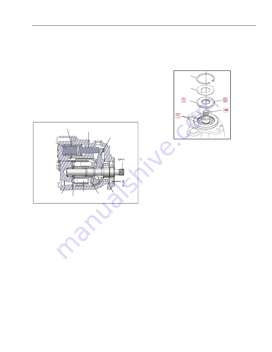
Bias spring
Servo piston
Swashplate
Output
Shaft
Piston
Slipper
Cylinder
Block
Endcap
Shaft
Seal
Bearing
Minimum
Angle
Stop
Valve plate
Figure 3-7. Drive Motor Cross Section
1
2
3
1. Snap Ring
2. Support Washer
3. Shaft Seal
Figure 3-8. Removing the Shaft Seal
Summary of Contents for 601S
Page 1: ...Service and Maintenance Manual Model 601S P N 3120746 November 22 2016 ...
Page 2: ......
Page 4: ... JLG Lift THIS PAGE LEFT BLANK INTENTIONALLY ...
Page 16: ...x JLG Lift 3120746 TABLE OF CONTENTS Continued This page left blank intentionally ...
Page 26: ...SECTION 1 SPECIFICATIONS 1 10 JLG Lift 3120746 Figure 1 3 Torque Chart ...
Page 36: ...SECTION 2 GENERAL 2 10 JLG Lift 3120746 Figure 2 7 Connector Installation ...
Page 40: ...SECTION 2 GENERAL 2 14 JLG Lift 3120746 This page left blank intentionally ...
Page 49: ...SECTION 3 CHASSIS TURNTABLE 3120746 JLG Lift 3 9 Figure 3 1 Torque Hub Drive Fairfield ...
Page 51: ...SECTION 3 CHASSIS TURNTABLE 3120746 JLG Lift 3 11 Figure 3 2 Torque Hub Drive Auburn Gear ...
Page 53: ...SECTION 3 CHASSIS TURNTABLE 3120746 JLG Lift 3 13 Figure 3 3 Drive Brake Assembly Ausco ...
Page 91: ...SECTION 3 CHASSIS TURNTABLE 3120746 JLG Lift 3 51 Figure 3 40 Swing Brake Assembly Ausco ...
Page 99: ...SECTION 3 CHASSIS TURNTABLE 3120746 JLG Lift 3 59 ...
Page 119: ...SECTION 3 CHASSIS TURNTABLE 3120746 JLG Lift 3 79 Figure 3 46 EFI Component Location ...
Page 122: ...SECTION 3 CHASSIS TURNTABLE 3 82 JLG Lift 3120746 Figure 3 47 ECM EPM Identification ECM EPM ...
Page 128: ...SECTION 3 CHASSIS TURNTABLE 3 88 JLG Lift 3120746 This page left blank intentionally ...
Page 132: ...SECTION 4 BOOM PLATFORM 4 4 JLG Lift 3120746 Figure 4 5 Boom Assembly Cutaway Sheet 1 of 2 ...
Page 133: ...SECTION 4 BOOM PLATFORM 3120746 JLG Lift 4 5 Figure 4 6 Boom Assembly Cutaway Sheet 2 of 2 ...
Page 145: ...SECTION 4 BOOM PLATFORM 3120746 JLG Lift 4 17 Figure 4 22 Rotator Assembly Helac ...
Page 148: ...SECTION 4 BOOM PLATFORM 4 20 JLG Lift 3120746 This page left blank intentionally ...
Page 174: ...SECTION 5 HYDRAULICS 5 26 JLG Lift 3120746 This page left blank intentionally ...
Page 176: ...SECTION 6 JLG CONTROL SYSTEM ADE 6 2 JLG Lift 3120746 Figure 6 1 EPBCS Block Diagram ...
Page 238: ...SECTION 7 SCHEMATICS 7 16 JLG Lift 3120746 Figure 7 15 Hydraulic Schematic Sheet 1 of 4 ...
Page 240: ...SECTION 7 SCHEMATICS 7 18 JLG Lift 3120746 Figure 7 17 Hydraulic Schematic Sheet 3 of 4 ...
Page 242: ...SECTION 7 SCHEMATICS 7 20 JLG Lift 3120746 This page left blank intentionally ...
Page 243: ......


