background image

SECTION 4 - BOOM & PLATFORM

3121142

– JLG Lift –

4-7

4.2

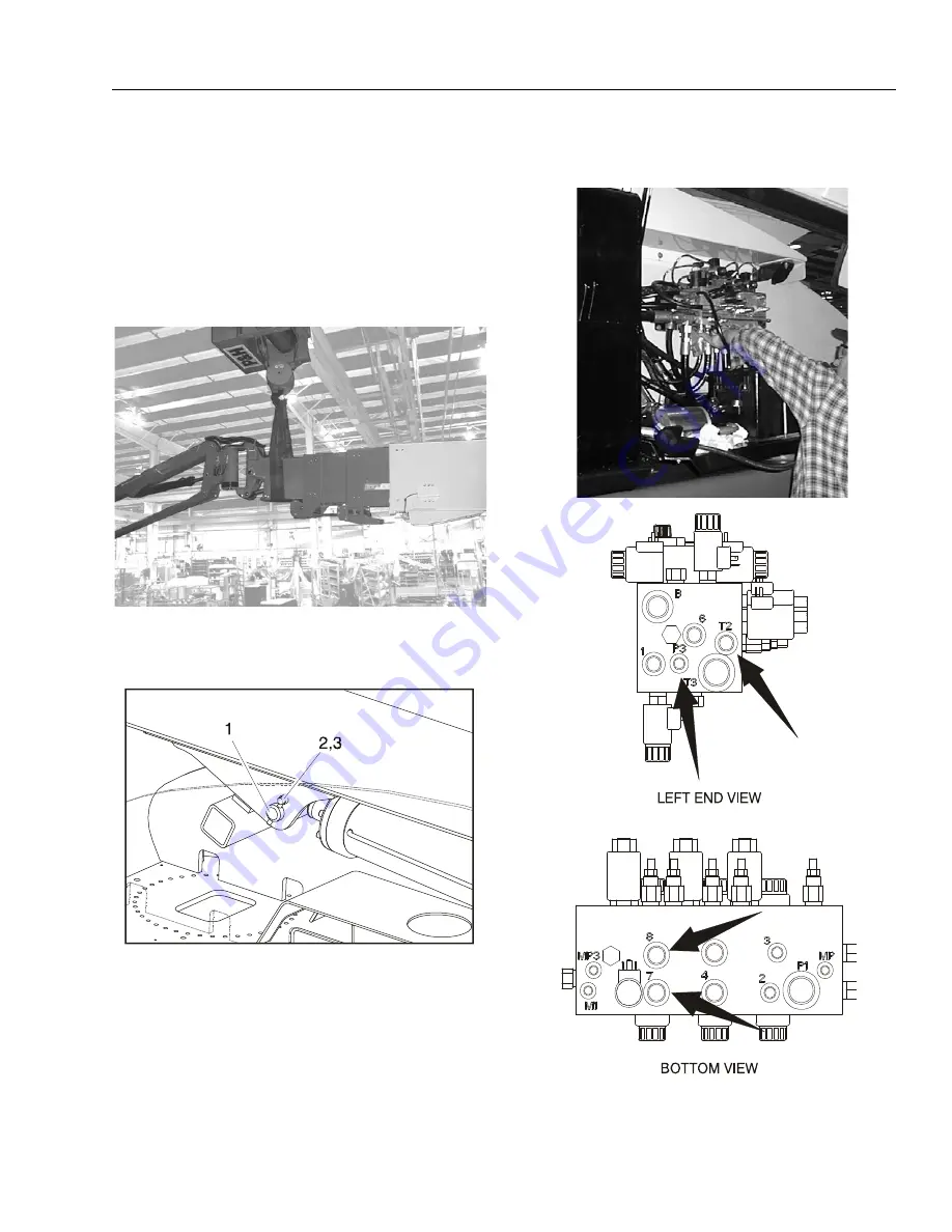
BOOM REMOVAL, DISASSEMBLY/ASSEMBLY, & 
CABLE REPLACEMENT

Removal

1.

Place machine on firm, level ground.

2.

Slightly elevate the boom and support the fly boom
with a crane or an adequate lifting device capable of
handling 6 - 7 tons.

3.

Place blocking under lift cylinder to hold it in place.

4.

Remove lift cylinder pin securing the lift cylinder rod to
the boom.

5.

Remove the boom end cover.

6.

Tag and disconnect the telescope, tank, and pressure
hoses as indicated below from the main valve and cap
ends.

1.

Pivot Pin

2.

Bolt

3.

Keeper Pin

Summary of Contents for 1200SJP

Page 1: ...Service and Maintenance Manual Models 1200SJP 1350SJP P N 3121142 November 8 2016 AS NZS...

Page 2: ......

Page 3: ...NER OPERATOR B HYDRAULIC SYSTEM SAFETY It should be noted that the machines hydraulic systems oper ate at extremely high potentially dangerous pressures Every effort should be made to relieve any syst...

Page 4: ...30 2004 Revised January 12 2006 Revised July 12 2006 Revised November 30 2006 Revised January 18 2007 Revised November 9 2007 Revised April 9 2008 Revised August 27 2008 Revised January 22 2009 Revis...

Page 5: ...1 Machine Preparation Inspection and Maintenance 2 1 General 2 1 Preparation Inspection and Maintenance 2 1 Pre Start Inspection 2 1 Pre Delivery Inspection and Frequent Inspection 2 1 Annual Machine...

Page 6: ...14 Oscillating Axle Lockout Test 3 15 3 11 Drive Hub Prior to S N 100131 3 16 Disassembly 3 16 Disassembly of Cover 3 16 Disassembly of the First Stage Planetary Assembly 7 3 16 Disassembly of Second...

Page 7: ...79 3 16 Swing Motor 3 82 Disassembly and inspection 3 82 Assembly 3 89 One Piece Stator Construction 3 96 3 17 Procedure For Setting Gear Backlash 3 97 3 18 Swing Drive Lubrication 3 98 3 19 Swing Bea...

Page 8: ...igh Pressure 3 153 DTC 524 Oil Pressure Low 3 154 DTC 562 Battery Voltage VBat Low 3 156 DTC 563 Battery Voltage VBat High 3 158 DTC 601 Microprocessor Failure FLASH 3 160 DTC 604 Microprocessor Failu...

Page 9: ...on Application 4 43 4 4 Boom Shimming Procedure 4 43 4 5 Jib Rotator Orientation 4 44 4 6 Jib Lift End of Stroke Dampening 4 44 4 7 Load Sensing Pin Removal and Installation 4 44 4 8 Powertrack Mainte...

Page 10: ...Adjustments Made at the Platform Valve Bank 5 31 5 5 Drive Pumps 5 32 Troubleshooting Procedure 5 32 Charge Pressure Relief Valve Adjustment 5 35 Mechanical Centering of Pump 5 36 Hydraulic Centering...

Page 11: ...31 6 12 Calibrating Steer 6 46 6 13 Calibrating Drive 6 49 6 14 Electronic Platform Leveling 6 52 Platform Leveling Fault Warning 6 52 Fault Response 6 52 CAN Errors 6 53 Additional Platform and Jib V...

Page 12: ...nt 7 1 Resistance Measurement 7 2 Continuity Measurement 7 2 Current Measurement 7 3 7 3 Applying Silicone Dielectric Compound to Electrical Connections 7 3 7 4 AMP Connector 7 4 Applying Silicone Die...

Page 13: ...Hub Assembly 3 22 3 17 Gearbox engaged 3 24 3 18 Gearbox Disengaged 3 25 3 19 Drive Hub S N 100128 to Present 3 28 3 20 Drive Hub Special Tools Sheet 1 of 4 3 46 3 21 Drive Hub Special Tools Sheet 2 o...

Page 14: ...1 of 5 3 127 3 76 EMR2 Fault Codes Sheet 2 of 5 3 128 3 77 EMR2 Fault Codes Sheet 3 of 5 3 129 3 78 EMR2 Fault Codes Sheet 4 of 5 3 130 3 79 EMR2 Fault Codes Sheet 5 of 5 3 131 3 80 1st page of Diagn...

Page 15: ...Seal Installation 5 14 5 17 Installation of Head Seal Kit 5 15 5 18 Piston Seal Kit Installation 5 15 5 19 Tapered Bushing Installation 5 16 5 20 Seating the Tapered Bearing 5 16 5 21 Rod Assembly Ins...

Page 16: ...7 4 7 6 AMP Connector 7 4 7 7 Connector Assembly Figure 2 7 5 7 8 Connector Assembly Figure 3 7 5 7 9 Connector Assembly Figure 4 7 5 7 10 Connector Disassembly 7 6 7 11 Connector Installation 7 7 7 1...

Page 17: ...lectrical Schematic Sheet 13 of 13 7 35 7 43 Hydraulic Schematic Boom Functions Sheet 1 of 2 7 36 7 44 Hydraulic Schematic Boom Functions Sheet 2 of 2 7 37 7 45 Hydraulic Schematic Axle Steer Control...

Page 18: ...xii JLG Lift 3121142 LIST OF FIGURES FIGURE NO TITLE PAGE NO This page left blank intentionally...

Page 19: ...ing Port Information Table 3 111 3 7 J1939 Diagnostic Lamp Configuration 3 138 4 1 Hose Cable Pull Chart 4 62 4 1 Hose Cable Pull Chart 4 62 5 1 Cylinder Head and Tapered Bushing Torque Specifications...

Page 20: ...xiv JLG Lift 3121142 LIST OF TABLES TABLE NO TITLE PAGE NO This page left blank intentionally...

Page 21: ...utput 87hp 65kW OilCapacity CoolingSystem w Filter TotalCapacity 5Quarts 4 5L 11Quarts 10 5L 16Quarts 15L AverageFuelConsumption 1 1gph 4 1lph IdleEngineRPM 1200 MidEngineRPM 1800 HighEngineRPM 2475 T...

Page 22: ...3 04m StowedLength TransportMode 1200SJP 1350SJP 34ft 11in 10 64m 38ft 11in 11 86m StowedLength WorkingMode 1200SJP 1350SJP 44ft 11in 13 69m 48ft 11in 14 91m Wheelbase 12ft 6in 3 81m Tailswing 5ft 6i...

Page 23: ...ts 13ft lbs 18Nm Asrequired StarterSolenoid Contacts Coil 95in lbs 9 5Nm 40in lbs 4Nm Asrequired Checkswingbearingboltsforsecurityafterfirst50hoursofoperationandevery600 hoursthereafter SeeSwingBearin...

Page 24: ...32 F 340cSt 1600SUS at40 C 104 F 46cSt 215SUS at65 C 150 F 22cSt 106SUS ViscosityIndex 170 Table 1 15 Mobil EAL H 46 Specs Type Synthetic Biodegradable ISOViscosityGrade 46 SpecificGravity 910 PourPoi...

Page 25: ...1 AxleOscillationCylinder 74 34 AxleExtendCylinder 92 42 LevelCylinder 89 40 Platform36x96 245 111 Platform36x72 195 89 1350Counterweight 8500 3856 1200Counterweight 5494 2492 T TAssy lessCwt 9450 428...

Page 26: ...SECTION 1 SPECIFICATIONS 1 6 JLG Lift 3121142 4 4 4 15 4 5 13 7 8 1 10 11 9 12 14 2 3 6 Figure 1 1 Lubrication and Operator Maintenance Diagram...

Page 27: ...50 hours of operation 2 Swing Gearbox Lube Point s Fill Plug Capacity 79 ounces 2 3 L Lube GL 5 Interval Check level every 150 hrs Change every 1200 hours of operation Fill to cover ring gear 3 Swing...

Page 28: ...00 hours of operation Comments Place Fill port at 12 o clock position and Check port at 8 o clock position Pour lubricant into fill port until it just starts to flow out of check port C Wheel Drive Hu...

Page 29: ...Cap Spin on Element Capacity 5 Quarts 4 5 L Cooling System 11 Quarts 10 5 L w Filter 16 Quarts 15 L Total Capacity Lube EO Interval Check level daily change every 500 hours or six months whichever co...

Page 30: ...ble Element Interval Every year or 600 hours of operation 12 Oil Change w Filter CAT Lube Point s Fill Cap Spin on Element Capacity 10 5 Quarts 10 L Lube EO Interval Check level daily change every 150...

Page 31: ...Point s Replaceable Element Interval Every 6 months or 300 hours of operation or as indicated by the condition indicator 15 Platform Filter Lube Point s Replaceable Element Interval Change after first...

Page 32: ...SECTION 1 SPECIFICATIONS 1 12 JLG Lift 3121142 Figure 1 3 Torque Chart Sheet 1 of 5 SAE Fasteners Torq ue To rqu e Torq ue To rqu e Torq ue Torq ue...

Page 33: ...SECTION 1 SPECIFICATIONS 3121142 JLG Lift 1 13 Figure 1 4 Torque Chart Sheet 2 of 5 SAE Fasteners Torq ue Tor que Torq ue Torqu e To rqu e...

Page 34: ...SECTION 1 SPECIFICATIONS 1 14 JLG Lift 3121142 Figure 1 5 Torque Chart Sheet 3 of 5 SAE Fasteners Cl amp L oa d To rque To rqu e Torq ue Torqu e Tor que Torq ue...

Page 35: ...SECTION 1 SPECIFICATIONS 3121142 JLG Lift 1 15 Figure 1 6 Torque Chart Sheet 4 of 5 METRIC Fasteners To rqu e To rqu e Torq u e To rq ue To rqu e To rq ue...

Page 36: ...SECTION 1 SPECIFICATIONS 1 16 JLG Lift 3121142 Figure 1 7 Torque Chart Sheet 5 of 5 METRIC Fasteners Torq ue To rqu e Tor qu e To rqu e To rqu e To rq ue...

Page 37: ...months or 150 hours whichever comes first out of service for a period of more than 3 months or when purchased used The frequency of this inspection must be increased as environ ment severity and frequ...

Page 38: ...eir containers until they are ready to be used Components Removal and Installation 1 Use adjustable lifting devices whenever possible if mechanical assistance is required All slings chains cables etc...

Page 39: ...t treated bolts studs and steel nuts in accordance with recommended shop practices See Torque Chart Sec tion 1 Hydraulic Lines and Electrical Wiring Clearly mark or tag hydraulic lines and electrical...

Page 40: ...t be changed after the first 50 hours of operation and every 300 hours unless specified oth erwise thereafter If it is necessary to change the oil use only those oils meeting or exceeding the specific...

Page 41: ...e cleaned with a solvent to remove all grease and oil filament wound bearing are a dry joint and should not be lubricated unless otherwise instructed i e sheave pins c Pins should be inspected to ensu...

Page 42: ...1 2 1 2 CoversorShields 1 2 1 2 Extend RetractChainorCableSystems 1 2 3 1 2 3 PlatformAssembly 9 Platform 1 2 1 2 Railing 1 2 1 1 2 Gate 5 1 1 5 Floor 1 2 1 1 2 Rotator 9 5 15 LanyardAnchoragePoint 2...

Page 43: ...icSystem 9 HydraulicPumps 1 9 1 2 9 HydraulicCylinders 1 9 7 2 1 2 9 1 2 9 CylinderAttachmentPinsandPinRetainers 1 9 1 2 1 2 HydraulicHoses Lines andFittings 1 9 12 1 2 9 12 1 2 9 12 HydraulicReservoi...

Page 44: ...reinstallation 2 Visualinspectionfordamage cracks distortionorexcessivewear 3 Checkforproperadjustment 4 Checkforcrackedorbrokenwelds 5 OperatesProperly 6 Returnstoneutralor off positionwhenreleased 7...

Page 45: ...S THE ADDITION OF A HYDRAULIC OIL COOLER CONSULT JLG SERVICE 180 F 82 C 40 F 40 C 30 F 34 C 20 F 29 C 10 F 23 C 0 F 18 C 10 F 12 C 20 F 7 C 30 F 1 C 40 F 4 C 50 F 10 C 60 F 16 C 70 F 21 C 80 F 27 C 90...

Page 46: ...C O N S U L TJLGS E R V IC E 180 F 82 C P R O L O N G E DO P E R A T IO NIN A M B IE N TA IRT E M P E R A T U R E S O F100 F 38 C O RA B O V E E X T E N D E DD R IV IN GW IT H H Y D R A U LICO ILT A N...

Page 47: ...en designed for stability requirements which consist of track width tire pressure and load capacity Size changes such as rim width center piece location larger or smaller diameter etc without written...

Page 48: ...ted to operation within the transport position If a signal from any axle extend sensing switch is lost when the boom beyond the transport position the axle set indicator will flash and drive steer fun...

Page 49: ...lected steering mode based on the position of the inside front wheel If the steer select switch is changed without the footswitch depressed or the EMS is off the wheels will not move until the footswi...

Page 50: ...o back NOTE For more detailed information concerning system adjust ment and operation refer to Section 6 JLG Control Sys tem 3 8 DRIVE ORIENTATION SYSTEM The Drive Orientation System DOS is intended t...

Page 51: ...SECTION 3 CHASSIS TURNTABLE 3121142 JLG Lift 3 5 This page left blank intentionally...

Page 52: ...SECTION 3 CHASSIS TURNTABLE 3 6 JLG Lift 3121142 Figure 3 5 Chassis Component Location Sheet 1 of 2...

Page 53: ...koutValve 5 TractionValve 6 SteerValve Rear 7 SteerAngleSensor RightRear 8 AxleLimitSwitch RightRear 9 AxleLimitSwitch LeftRear 10 SteerAngleSensor LeftRear 11 ChassisModule 12 Swivel CollectorRing 13...

Page 54: ...SECTION 3 CHASSIS TURNTABLE 3 8 JLG Lift 3121142 Figure 3 7 Turntable and Boom Component Location Sheet 1 of 2...

Page 55: ...lBox 19 BoomAngleSensor Left 20 BrokenCableProximitySwitch 21 BoomLengthSensor 22 BoomAngleSensor Right 23 Headlight 24 DeutzEMR2Module 25 110V 220VGenerator 26 GeneratorControlBox 27 Alternator 28 Th...

Page 56: ...142 3 1 2 6 D E T A ILA D E T A ILB 5 4 Figure 3 9 Oscillating Axle Sheet 1 of 2 AXLESTOPSHIMMINGPROCEDURE 1 ALLFOURWHEELSOFTHEMACHINESHOULD BEONALEVEL SURFACEWITHTHETURNTABLESQUARETOTHEFRAME 2 SHIMAX...

Page 57: ...dePlatesofAxleWeldments Typical16Places D AssembletoFrontandRearPlatesofAxleBoxes Typical8Places E AssembletoTopPlateofAxleWeldment Typical4Places Torque Selectappropriatebolttoensure0 5 0 062inches 1...

Page 58: ...SECTION 3 CHASSIS TURNTABLE 3 12 JLG Lift 3121142 Figure 3 11 Axle Loctite Application...

Page 59: ...2 Angle Sensor Assembly 3 Steer Cylinder 4 Steer Cylinder Pivot Pin 5 King Pin 6 Axle Figure 3 12 Steering Installation Table 3 2 Steering Assembly Notes A ApplyLoctite 242 B ApplyLoctite 271 C Apply...

Page 60: ...OSCILLATING AXLE BLEEDING PROCEDURE AND LOCKOUT TEST Lockout Cylinder Bleeding To start the test the axle must be fully oscillated in one direc tion Start with oscillating the axle so that the left lo...

Page 61: ...RD position and carefully drive machine up ascension ramp until left front wheel is on top of block 5 Telescope the boom out of the transport position 6 Drive machine off of block and ramp back onto t...

Page 62: ...disassembly of the hub is discouraged reinstalla tion of the shaft nut 4 requires a special tool and a torque of 626 ft lbs 876 Nm for proper reassembly These com ponents Will Fail if not properly re...

Page 63: ...l seal rings 22 and screw plugs 21 6 Before installation of motor CHECK THAT THERE IS 1 2 mm OF CLEARANCE BETWEEN THE MOTOR SPLINE SHAFT SHOULDER AND THE COUPLER 62 7 Install the motor and reconnect h...

Page 64: ...SECTION 3 CHASSIS TURNTABLE 3 18 JLG Lift 3121142 Figure 3 13 Drive Hub Sheet 1 of 2...

Page 65: ...Used 30 Ring Gear 31 Not Used 32 Not Used 33 O ring 34 thru 40 Not Used 41 Planet Carrier 42 Sun Gear 43 Sun Gear 44 Not Used 45 Planet Pin 46 Roller Bearing 47 Retaining Ring 48 Retaining Ring 49 No...

Page 66: ...assemble it to the gearbox being careful not to damage the seal already fitted 2 Torque the bolts to 63 5 ft lbs 86 Nm torque Installation of the Wheel Drive on the Machine 1 Clean the mating surface...

Page 67: ...he minimum operating costs and a longer unit life Photographic documentation and drawings are supplied for educational purposes so as to safely and properly carry out maintenance operations Minor devi...

Page 68: ...SECTION 3 CHASSIS TURNTABLE 3 22 JLG Lift 3121142 Figure 3 16 Hub Assembly 1 M18x1 5 Filling drainingandoillevelplugs 2 7 16 20UNF 2B Brakeport...

Page 69: ...ew minutes stop and check the oil level 5 If necessary refill with lubricant oil Approximate oil capacity 2 liters 10 Gearbox Disengagement The gearbox is supplied with mechanical disengagement THE DI...

Page 70: ...1 Unscrew the 2 socket head screws M8x16 4 grade 8 8 of the end cover 7 with a male hex head wrench 2 Rotate the cap nut 5 3 Take out the cap nut 5 4 Turn the cap nut 5 upside down As result the pin 3...

Page 71: ...ble the gearbox Changing the Lubricating oil 1 Check that the gearbox axis is horizontal Rotate the gearbox housing until the drain plug is on the bottom of the vertical axis of the end cover 2 Unscre...

Page 72: ...a that is in line with work and health safety in the workplace guidelines Disassembly Procedure NOTE Below are all the steps to follow during Disassembly and Assembly Numbers in brackets in the text c...

Page 73: ...il it compresses the springs 45 2 Remove the circlip 47 and remove the special tool 3 Remove the spring retainer disc 46 4 Mark the position of the springs 45 as a reference for the reassembly 5 Remov...

Page 74: ...eSunGear 18 2ndReductionAssembly 19 Circlip 20 3rdReductionAssembly 21 Spacer 22 RingNut 23 GearboxHousing 24 Bearing 25 Spacer 26 Spacer 27 O ring 28 Spacer 29 HalfSeal 30 SealRing 31 FlangedHub 32 D...

Page 75: ...move the spacer 39 from the brake piston 44 9 Remove the internal O Ring seal 41 and the backup ring 40 from their seat in the spacer 39 10 Remove the external O Ring seal 38 and the backup ring 37 fr...

Page 76: ...l tool 6689960240 15 Tighten the 2 screws M5x16 grade 8 8 of the cover by a torque wrench to 18 4 ft lbs 25 Nm 16 By using pliers remove the elastic ring 11 from the splined shaft 14 17 Remove the spe...

Page 77: ...he cap nut 5 20 Remove the pin 3 21 Remove the O ring seal 2 from its seat in the end cover 7 22 Unscrew the draining filling level oil plugs 6 by a male hex head wrench 23 Unscrew the 10 screws M10X2...

Page 78: ...9 from its seat in the end cover 7 26 Remove the 1st stage sun gear 10 27 Remove the 1st reduction assembly 16 28 Remove the 2nd stage sun gear 17 29 Remove the 2nd reduction assembly 18 30 By using...

Page 79: ...ub 31 NOTE In order to proceed with the gearbox disassembly it is now necessary to remove it from the machine and bring it to a properly equipped workshop 33 By using a drill remove the caulkings on t...

Page 80: ...f seal 29 from the flanged hub 31 41 By using a screwdriver remove the 2nd half seal 29 from the gearbox housing 23 NOTE The gearbox disassembly ends with the above operation All items are now availab...

Page 81: ...ces sary metallic brushes or solvent surfaces in contact with or C must be perfectly clean and dry b Make sure that sealing surfaces D of metal rings E are free from scratches dinges or foreign sub st...

Page 82: ...5 Carefully clean the metallic faces of the lifetime seal 29 and lube the surfaces with oil 6 Insert the seal ring 30 in its seat in the flanged hub 31 7 Apply grease TECNOLUBE SEAL GS730 on the seal...

Page 83: ...OMING OUT OF THE GEARBOX HOUSING 23 DURING THE FOLLOWING STEPS 10 By using a hoist place the torque multiplier ATZ 09 016 0 on the ring nut 22 11 By using the mutiplier ATZ 09 016 0 tighten the ring n...

Page 84: ...of the 3rd reduction 20 in the flanged hub s pin 31 15 By using a rubber hammer and a metal stopper push the planet assemblies of the 3rd reduction 20 against the shoulder until assembly is complete...

Page 85: ...ssemble the O ring seal 9 into its seat in the end cover 7 22 Place the end cover 7 on the gearbox housing 23 23 Tighten the 10 socket head screws M10x25 1 grade 12 9 by a torque wrench at 62 7 ft lbs...

Page 86: ...seat and the pin 3 with grease type MOLYKOTE G6000 Wait 15 minutes for it to completely dry Insert the pin 3 in its seat in the end cover 7 27 Assemble the cap nut 5 28 Torque the 2 screws M8x16 4 gra...

Page 87: ...t 6689960240 32 Insert the 2nd washer 12 correctly in the splined shaft 14 33 Torque the 2 screws M5x16 grade 8 8 of the cover to 18 4 ft lbs 25 Nm 34 By using pliers assemble the elastic ring 11 into...

Page 88: ...e discs package according to the fol lowing order first insert one sintered bronze disc with external teeth 33 39 Then insert an internally toothed steel disc 32 Repeat the operation until all 5 sinte...

Page 89: ...a rubber hammer and a metal stopper push the spacer 39 against the flanged hub 31 paying atten tion not to damage the seals already fitted 44 Lube the seal seats into the flanged hub 31 and assem ble...

Page 90: ...tion not to damage the seals already fitted 46 By using a rubber hammer and a metal stopper push the brake piston 44 against the flanged hub 31 paying attention not to damage the seals already fitted...

Page 91: ...and Running In If work on the brake was undertaken it is important to check that there are no oil leaks Follow the procedure below 1 Connect the pressure pilot line with the manometer with a base scal...

Page 92: ...SECTION 3 CHASSIS TURNTABLE 3 46 JLG Lift 3121142 Figure 3 20 Drive Hub Special Tools Sheet 1 of 4...

Page 93: ...SECTION 3 CHASSIS TURNTABLE 3121142 JLG Lift 3 47 Figure 3 21 Drive Hub Special Tools Sheet 2 of 4...

Page 94: ...SECTION 3 CHASSIS TURNTABLE 3 48 JLG Lift 3121142 Figure 3 22 Drive Hub Special Tools Sheet 3 of 4...

Page 95: ...SECTION 3 CHASSIS TURNTABLE 3121142 JLG Lift 3 49 Figure 3 23 Drive Hub Special Tools Sheet 4 of 4...

Page 96: ...L Tools Tools required for assembling and disassembling the wheel gear RRTD1701TB 1 Hammer 2 Clamps for inner retention rings 3 Clamps for outer retention rings 4 Electric or pneumatic screwdriver 5 S...

Page 97: ...ECTION 3 CHASSIS TURNTABLE 3121142 JLG Lift 3 51 LOCTITE 2701 197 5 210 110 30 130 210 N 4 Hole to 90 40 25 5x45 M 1320 M 1321 Figure 3 26 Bearing Spacer Mountng CO16117 Figure 3 27 Assembly Diagram 1...

Page 98: ...Figure 3 28 Wrench For Ring Nut A A 50 180 275 305 n 12 Fori a 30 35 20 H7 0 021 0 n 12 Hole to 30 n 12 Hole to 30 6 5 n 12 Spot facing to 30 10 5 n 4 Hole to 90 M10 20 6 5 T U 15 32 10 5 80 3 0 3 0 3...

Page 99: ...SECTION 3 CHASSIS TURNTABLE 3121142 JLG Lift 3 53 M 1020 M 1126 M 1125 VTCEI M6X12 n 12 VTCEI M10X60 n 4 M 1126 Figure 3 32 Assembly Diagram 2...

Page 100: ...ift 3121142 46 48 5 70 5 80 50 88 5 3 5 M8 20 0 0 1 20 0 1 0 2 93 5 105 8 5 13 5 9 20 8 5 5 t u 12 2 5x15 39 5 M 1546 M 1548 M 1547 40 5 46 VTCEI M8X16 n 1 Figure 3 33 Tools For Assembling Bearing 3rd...

Page 101: ...he lubricant in a container 2 Release the screws to disassemble the motor flange tak ing care not to damage the O Ring 3 Release the screws from the release cover and pull the pin out 4 Remove the BR2...

Page 102: ...SECTION 3 CHASSIS TURNTABLE 3 56 JLG Lift 3121142 Figure 3 34 Reggiana Riduttori Hub Sheet 1 of 2...

Page 103: ...0 Input Shaft Bearing 21 Ring 22 Disengagement Spring 23 Disengagement Shaft 24 Spindle Oil Seal 25 Tapered Roller Bearing 26 Bearing Support 27 Ring Nut 28 Sphere 29 Screw 30 Pinion 31 Reduction Gear...

Page 104: ...Remove the release joint together with the spring 8 Disassemble the 40 outer snap rings and using an extractor remove the planetary gears from the spindle pins 9 Loosen the M6x6 socket headless screw...

Page 105: ...14 Fit the ball bearing into the input shaft and lock it with a 40 outer snap ring Then mount the motor shaft in the spindle and lock with a BR68 ring Lubricate the bearing Assembly 1 Make sure all t...

Page 106: ...160 inner snap ring Check the brake leakage if any as well as the static torque and minimum opening pressure 6 Prepare the hub support mounting on it the two roller bearing outer tracks Place the fir...

Page 107: ...at the final torque of 30daNm alter nate tightening and some setting turns Check the roll torque with seal which must be within 1 1 5 daNm NOTE Place the ring nut with its convex part facing the roll...

Page 108: ...a mark between the snap ring and the bearing Fit the greased spring and the release joint Use grease to fit the O Ring 2 275 in the hub support seat 15 Place the hub onto the support making the two h...

Page 109: ...ng it with the BR250 ring 19 Fit the O Ring 2 163 suitably greased onto the motor coupling flange S D LC KC Mount the flange on the spindle with 6 M8x25 socket cap screws at the torque of 2 4daNm with...

Page 110: ...ECTION 3 CHASSIS TURNTABLE 3 64 JLG Lift 3121142 1 SwingDrive 2 InnerRaceBearingBolt 3 SwingBearing 4 OuterRaceBearingBolt 5 TurntableLockPin 6 RemoteBearingLubricationFittings Figure 3 36 Swing Syste...

Page 111: ...ith consistency LEAK TEST MAIN UNIT The purpose of a leak test is to make sure the unit is air tight You can tell if your unit has a leak if the pressure gauge read ing on your air checker starts to f...

Page 112: ...ench 4 Using a wrench loosen jam nuts on Elbow Fittings 36 and remove fittings from Brake 26 and Motor Control Valve 32 5 Remove O ring Plugs 21 from Motor Control Valve 32 6 Remove Motor Control Valv...

Page 113: ...otor 10 2 Pull Motor 10 straight up and remove Motor 10 from Brake 26 3 Remove Gasket 31 from between Brake 26 and Motor 10 4 Remove Brake 26 from Main Torque Hub Assembly and dump oil out of Brake 26...

Page 114: ...4 Remove Thrust Washer 8 from end of Sun Gear 13 5 Remove Sun Gear 13 6 Remove Thrust Washers 16 and Thrust Bearing 15 from between Input Cover 6 and Carrier 3A Subas sembly 7 Remove Ring Gear 4 from...

Page 115: ...Bearing Cone 1D during this step 4 Remove the Bearing Cone 1F from the Housing 1G 5 Invert the Housing 1G and remove the Lip Seal 1B if not already removed when Output Shaft 1A was pressed out of Hou...

Page 116: ...Planet Shaft 3E from the Carrier 3A Use a small punch to remove the Roll Pin 3G from the Planet Shaft 3E 3 Slide the Planet Gear 3F two Ball Indented Thrust Washers 3H and the two Thrust Washers 3B o...

Page 117: ...8 Press or tap the Bearing Cone 1F onto the Output Shaft 1A until it is seated in the Bearing Cup 1E 9 Install Bearing Spacer 1H onto Output Shaft 1A and against Bearing Cone 1F 10 Install Retaining R...

Page 118: ...e end of Cluster Gear 3F facing the roll pin hole in the carrier place the cluster gear into position in Carrier 3A and push Planet Shaft 3E through the Clus ter Gear 3F without going all the way thro...

Page 119: ...ASSIS TURNTABLE 3121142 JLG Lift 3 73 3A Carrier 3B TangedThrustWasher 3C NeedleBearing 3D ThrustWasher 3E PlanetShaft 3F ClusterGear 3G RollPin 3H BallIndentedWasher Figure 3 43 Swing Drive Carrier S...

Page 120: ...stallation The side of the Ring Gear 4 with an X or punch mark stamped on it should be up 9 While holding Ring Gear 4 and Cluster Gears 3F in mesh place small end of Cluster Gears 3F into mesh with th...

Page 121: ...NTABLE 3121142 JLG Lift 3 75 2 InternalGear 4 RingGear 5 O Ring 6 InputCover 8 HexBolt 13 SunGear 15 ThrustBearing 16 ThrustWasher 17 HexBolt 18 ShoulderBolt 19 Lockwasher 20 PipePlug Figure 3 44 Swin...

Page 122: ...the holes 3 Place Motor 10 into Brake pilot against the Gasket 31 4 Assemble Lift Lugs 28 onto Hex Bolts 29 Assemble Hex Bolts 29 with Lift Lugs through the Motor 10 and Brake 26 against the motor fla...

Page 123: ...o 15 ft lbs 18 to 21 Nm 4 Assemble Tube 35 into Elbow Fittings 36 and torque 13 to 15 ft lbs 18 to 21 Nm 5 Install O ring Plugs 21 into Motor Control Valve 32 and torque 30 to 31 ft lbs 42 to 43 Nm 6...

Page 124: ...e Remove hydraulic supply from brake checking to ensure that the friction plates 3 6 have engaged thus preventing rota tion of brake shaft 1 RELEASE PRESSURE DURING BENCH TESTING SHOULD BE LIMITED TO...

Page 125: ...sembly can now be fully dismantled and parts examined 2 Remove cylinder housing 8 and piston 9 subassembly and dismantle if required removing O ring seals 15 17 and backing rings 16 18 as necessary 3...

Page 126: ...ect brake operation it is important that the backing rings are assembled opposite ti the pressurized side of piston 9 5 Correctly orientate piston 9 aligning spaces with the two dowel pin holes and as...

Page 127: ...5 Gasket 6 OuterPlate 7 Gasket 8 Cylinder 9 Piston 10 DeepGrooveBallBearing 11 InternalRetainingRing 12 RotaryShaftSeal 13 SocketHeadCapScrew 14 ShakeproofWasher 15 O Ring 16 BackingRing 17 O Ring 18...

Page 128: ...cross the Torq link components from end cover 2 to housing 18 to facilitate reassembly orientation where required Loosen two shuttle or relief valve plugs 21 for disassembly later if included in end c...

Page 129: ...ded the orifice plug in the end cover 2 must not be removed as they are serviced as an integral part of the end cover 1 SpecialBolts 2 EndCover 3 SealRing Commutator 4 SealRing 5 CommutatorRing 6 Comm...

Page 130: ...close inspection of end cover commutator manifold and rotor set 7 Remove commutator ring 6 Inspect commutator ring for cracks or burrs 8 Remove commutator 5 and seal ring 3 Remove seal ring from commu...

Page 131: ...ing service procedures Marking the surface of the rotor and stator that is facing UP with etching ink or grease pen cil before removal from Torqlink will ensure correct reas sembly of rotor into stato...

Page 132: ...ns of rust and corrosion which might prevent its withdrawal through the seal and bear ing Crocus cloth or fine emery paper may be used 15 Remove coupling shaft 12 by pushing on the output end of shaft...

Page 133: ...anging dimen sional characteristics Inspect tapped holes for thread damage If the housing is defective in these areas dis card the housing assembly 21 If the housing 18 assembly has passed inspection...

Page 134: ...the beginning of bearing bushing counter bore should be measured and noted before removing the bearings bushings This will facilitate the correct reassembly of newbearings bushings 22 If the bearings...

Page 135: ...ng components were removed for replacement thoroughly coat and pack a new outer bearing bushing 19 with clean corrosion resistant grease recommended in the material section Press the new bearing bushi...

Page 136: ...flush to 0 03 inch 76 mm below the housing wear plate contact face Use the opposite end of the bearing mandrel that was used to press in the outer bearing bushing 19 3 Press a new dirt and water seal...

Page 137: ...UP WASHER 25 WHEN DISASSEMBLED MUST BE ASSEMBLED WITH A NEW BACKUP WASHER 17 NEW BACKUP WASHER 25 AND NEW SEAL 16 6 Assemble thrust washer 14 then thrust bearing 15 that was removed from the Torqlink...

Page 138: ...nsert it into the housing 18 seal ring groove NOTE One or two alignment studs screwed finger tight into housing 18 bolt holes approximately 180 degrees apart will facilitate the assembly and alignment...

Page 139: ...n the original rotor drive link spline contact A rotor set without a counterbore and that was not etched before disassembly can be reinstalled using the drive link spline pattern on the rotor splines...

Page 140: ...onto manifold 7 with seal ring side up 19 If shuttle valve components items 21 were removed from the end cover 2 turn a plug 21 loosely into one end of the valve cavity in the end cover A 3 16 inch A...

Page 141: ...her components into place with a final torque of 22 26 ft lbs 45 55 ft lbs 61 75 N m for the seven 3 8 24 threaded bolts NOTE The special bolts required for use with the relief or shuttle valve 24 end...

Page 142: ...nk 10 splines NOTE If the manifold side of the rotor was etched during Torqlink disassembly this side should be up If the rotor is not etched and does not have a counterbore use the drive link spline...

Page 143: ...stamped with an X on the surface below the teeth and marked with yellow paint in the tooth space 3 Torque the shoulder screw shown below to 660 foot pounds 896 Nm with Loctite 271 4 Remove the turntab...

Page 144: ...rbox is to be filled with 79 ounces 2 3 L of API Service Classification GL 5 Extreme Pressure Gear Lube Fill to cover the ring gear The Swing Brake is to be filled half full 2 7 ounces 80 ml with DTE2...

Page 145: ...existing bolts for looseness 1 Check the frame to bearing attach bolts as follows a Fully elevate the main boom See Figure 3 54 b At the position indicated on Figure 3 54 try to insert a 0 0015 feele...

Page 146: ...TURNTABLE 3 100 JLG Lift 3121142 D IA LIN D IC A T O R M E A S U R IN GP O IN T F E E LE RG A U G E M E A S U R IN GP O IN T BO O M F U LL YE LE V A T E D Figure 3 54 Swing Bearing Tolerance Boom Plac...

Page 147: ...SSIS TURNTABLE 3121142 JLG Lift 3 101 D IA L IN D IC A T O R F E E LE R G A U G E M E A S U R IN G P O IN T T E LE S C O P E F U LL Y E X T E N D E D Figure 3 55 Swing Bearing Tolerance Boom Placement...

Page 148: ...tation 5 If bearing inspection shows no defects reassemble and return to service Swing Bearing Removal 1 From Ground Control station operate the boom ade quately to provide access to frame opening to...

Page 149: ...RNTABLE 3121142 JLG Lift 3 103 CENTER OF GRA VITY C L ROTA TION 1 45 cm 1200SJP 8 13 33 cm 1350SJP 1350SJP Upperstructure 30 250 lbs 13 721 kg 1200SJP Upperstructure 26 150 lbs 11 861 kg Figure 3 57 S...

Page 150: ...ard the bolts Use suitable lifting equipment to remove the bearing from the frame then move the bearing to a clean suitably supported work area Swing Bearing Installation NOTE The swing bearing weighs...

Page 151: ...ctite 271 to the new bearing bolts and install the bolts and washers through the turntable and inner race of the bearing 8 Following the Torque Sequence diagram shown in Fig ure 3 58 Swing Bearing Tor...

Page 152: ...settings 5 0 and 8 0 degrees The smaller angle is used for the purpose of warning the operator by means of the chassis tilt light in the platform display panel Additionally when used in conjunction wi...

Page 153: ...enter body 1 from housing 3 4 Cut off old seals 2 3 5 5 Assemble lip seals 2 in direction shown in Figure 3 59 Rotary Coupling Seal Installation 6 Reassemble O ring 4 7 Heat cap seals 5 in hydraulic o...

Page 154: ...SECTION 3 CHASSIS TURNTABLE 3 108 JLG Lift 3121142 1 Center Body 2 Seal 3 Housing 4 O ring 5 Seal 6 Thrust Ring 7 Snap Ring Figure 3 60 Rotary Coupling Cutaway...

Page 155: ...109 5 6 8 8 3 5A 5B 4 1 9 8 1 2 1 Loctite 242 2 Bolt 3 Bolt 4 Swivel Bracket 5 Rotary Coupling Collector Ring Assembly 5A Rotary Coupling 5B Rotary Circuit Contactor 6 Locknut 7 Not Used 8 Flatwasher...

Page 156: ...SECTION 3 CHASSIS TURNTABLE 3 110 JLG Lift 3121142 1 2 3 4 5 7 7 1 2 3 7 6 5 1 3 2 1 6 2 4 6 7 4 3 2 5 1 Figure 3 62 Rotary Coupling Port Location...

Page 157: ...0 hours of service blow out the inside of the genera tor If operating in a hostile environment clean monthly Table 3 6 Coupling Port Information Table Port No Outlets Port Size Description Operating P...

Page 158: ...ith slip rings View alignment through the air vents in the stator barrel The brushes must ride completely on the slip rings INSPECTING BRUSHES Remove the end panel Inspect the wires Remove the brush h...

Page 159: ...SECTION 3 CHASSIS TURNTABLE 3121142 JLG Lift 3 113 Figure 3 63 Inspecting Generator Brushes Replacing Brushes and Cleaning Slip Rings 1 BrushHolderAssembly 2 Brushes 3 SlipRings...

Page 160: ...f the system the auxiliary power functionality differs from the primary power functional ity The auxiliary power lift down function supplies pilot pres sure to the lift cylinder allowing gravity to lo...

Page 161: ...R E FA U XP U M P V IE WA A BA TT E R YH E A T E RC A B LE BA TT E R YH E A T E RC A B LE B A T T E R Y VIEW B B T A N KH E A T E R B A TT E R YH E A T E R BA TT E R YH E A T E R H Y D R A U LICO IL...

Page 162: ...bled during this period On Deutz engines the glow plugs will continue post glow after the engine has started for three times the machine digit setting Checking Oil Level 1 Switch the engine off before...

Page 163: ...6 Drain the oil 7 Close the oil drain valve 8 Pour in new engine oil Refer to Section 1 for capacity and refer to Figure 3 67 Engine Oil Viscosity for the proper grade Changing the Oil Filter 1 Wipe...

Page 164: ...aping fuel 4 Clean any dirt from the filter carrier sealing surface 5 Apply a light film of oil or diesel fuel to the rubber gas ket of the new filter cartridge 6 Manually screw in the new filter unti...

Page 165: ...d by means of the control rod travel sensor situated together with the rotation magnets in a hous ing of the actuator The EMR2 is equipped with safety devices and measures in the hardware and software...

Page 166: ...POWERSUPPLY COOLANTTEMPERATURE SENSOR CONTROLRODPOSITION SENSOR ACTUATOR FLYWHEELSPEED SENSOR OILPRESSURE SENSOR JLGSYSTEMUSESJLGANALYZERTOREPORTFAULTS DIAGNOSISINTERFACE CAN BUS JLGSYSTEMUSESTHIS TOC...

Page 167: ...nplug the vehicle side engine m odule connector V erify there is 12V across pins 1 G round 14 B attery V erify there is 60 O hm s across pins 12 13 C A N H igh Low C an you start the engine V erify th...

Page 168: ...SECTION 3 CHASSIS TURNTABLE 3 122 JLG Lift 3121142 Figure 3 70 Deutz EMR 2 Vehicle Side Connection Diagram...

Page 169: ...SECTION 3 CHASSIS TURNTABLE 3121142 JLG Lift 3 123 Figure 3 71 Deutz EMR 2 Engine Side Connection Diagram Sheet 1 of 2...

Page 170: ...SECTION 3 CHASSIS TURNTABLE 3 124 JLG Lift 3121142 Figure 3 72 Deutz EMR 2 Engine Side Connection Diagram Sheet 2 of 2...

Page 171: ...SECTION 3 CHASSIS TURNTABLE 3121142 JLG Lift 3 125 Figure 3 73 EMR 2 Engine Plug Pin Identification...

Page 172: ...SECTION 3 CHASSIS TURNTABLE 3 126 JLG Lift 3121142 Figure 3 74 EMR 2 Vehicle Plug Pin Identification...

Page 173: ...SECTION 3 CHASSIS TURNTABLE 3121142 JLG Lift 3 127 Figure 3 75 EMR2 Fault Codes Sheet 1 of 5...

Page 174: ...SECTION 3 CHASSIS TURNTABLE 3 128 JLG Lift 3121142 Figure 3 76 EMR2 Fault Codes Sheet 2 of 5...

Page 175: ...SECTION 3 CHASSIS TURNTABLE 3121142 JLG Lift 3 129 Figure 3 77 EMR2 Fault Codes Sheet 3 of 5...

Page 176: ...SECTION 3 CHASSIS TURNTABLE 3 130 JLG Lift 3121142 Figure 3 78 EMR2 Fault Codes Sheet 4 of 5...

Page 177: ...SECTION 3 CHASSIS TURNTABLE 3121142 JLG Lift 3 131 Figure 3 79 EMR2 Fault Codes Sheet 5 of 5...

Page 178: ...limit values Since experience has shown that rape seed oil methylester RME exceeds the limit values less often that other esters it is expressly recommended to use only rape seed oil methyester DEUTZ...

Page 179: ...y by heat and water Penetration by water is usually caused by condensation of the water in the air Water does not dissolve in fuel so that the pene trating water collects at the bottom of the tank The...

Page 180: ...xternal Hardware Input Output This identifies the hardware that either sends an input to the ECM or is driven by and ECM output Check Condition This defines what condition to troubleshoot the fault co...

Page 181: ...SSIS TURNTABLE 3121142 JLG Lift 3 135 DTC XXXX Diagnostic Condition Note Helpful tips used to aid troubleshooting Yes No Troubleshooting flow chart Figure 3 81 2nd Page of Diagnostic Information for a...

Page 182: ...Code PFI PortFuelInjection DVOM DigitalVoltageandOhmMeter highimpedance PGN ParameterGroupNumber ECI EControlsInc PWM PulseWidthModulated ECIPP EControlsInc ProprietaryProtocol RAM RandomAccessMemory...

Page 183: ...ilTemperature Vsw Switched IgnitionVoltage FSS FaultSnapshot WGP Waste GatePressure FT FuelTemperature GCP GlobalControlPlatform HDGCP Heavy DutyGlobalControlPlatform On RoadHeavy Duty HEGO HeatedExha...

Page 184: ...on the applica tion and engine calibration There are 4 CAN SPN FMI lists available in the DGC software set contact EControls Inc for a list of CAN SPN FMIs The data capture at the occurrence of a faul...

Page 185: ...ading is cool the sensor reads higher voltage and lower when warm This fault will help protect the engine in the event of over tem perature When the coolant exceeds x deg F and engine RPM exceeds y RP...

Page 186: ...thermistor tem perature sensitive resistor located in the engine coolant Some engines use an ECT sensor that is located in the coolant near the thermostat Some engines use a CHT Cylinder Head Tempera...

Page 187: ...C Tsensor fromharness K eyO n E ngineO ff S ystemM ode S topped S ensor signal circuit shorted toground check w ireharnessfor ground short F aultyE C M F aultyE C T S ensor Yes No D oesD S Tdisplayan...

Page 188: ...located in the coolant near the thermostat Some engines use a CHT Cylinder Head Temperature sensor that is located in the coolant in the cylin der head If the engine is equipped with an ECT sensor th...

Page 189: ...SECTION 3 CHASSIS TURNTABLE 3121142 JLG Lift 3 143...

Page 190: ...voltage divider circuit or 2 a non contact hall effect sensor to determine throttle actu ator position and is located within the throttle actuator There are two types of throttle actuators 1 actuator...

Page 191: ...SECTION 3 CHASSIS TURNTABLE 3121142 JLG Lift 3 145...

Page 192: ...ion Sensor uses either 1 a variable resistor and voltage divider circuit or 2 a non contact hall effect sensor to determine throttle actu ator position and is located within the throttle actuator Ther...

Page 193: ...SECTION 3 CHASSIS TURNTABLE 3121142 JLG Lift 3 147...

Page 194: ...en warm This fault will help protect the engine in the event of over tem perature When the coolant exceeds x deg F and engine RPM exceeds y RPM for the latch time this fault will set Diagnostic Aids I...

Page 195: ...time the engine RPM exceeds the limit set in the diagnostic calibration for the latch time or more This speed overrides any higher max governor speeds pro grammed by the user This fault is designed to...

Page 196: ...o determine crankshaft position with respect to TDC cylinder 1 compression and the rotational engine speed Determina tion of the crankshaft position and speed is necessary to prop erly activate the ig...

Page 197: ...ition that set fault based on fault snapshot Is crank sensor a VR magnetic pick up Is the wiring OK Faulty wireharness twist circuit Is wiring between sensor and ECM properly twisted No Does fault onl...

Page 198: ...respect to TDC cylinder 1 compression and the rotational engine speed Determina tion of the crankshaft position and speed is necessary to prop erly activate the ignition fuel injection and throttle g...

Page 199: ...ion in the oil flow path or can be a sign of a malfunc tioning oiling system Additionally for normally open type oil pressure switches a high pressure indication while the engine is off is a symptom o...

Page 200: ...be undesirable because it can cause oil to leak past seals and rings can be a result of a restriction in the oil flow path or can be a sign of a malfunc tioning oiling system For systems that use a t...

Page 201: ...limit set in diagnostic calibration Yes Does DTC 524 reset Faulty connection at sensor Faulty ECM Faulty Oil Pressure Switch open circuit Faulty engine oiling system verify with mechanical gauge No Y...

Page 202: ...und audible warning or illuminate secondary warning lamp disable adaptive fueling correction for remainder of key cycle Non emissions related fault The battery voltage powers the ECM and must be withi...

Page 203: ...SECTION 3 CHASSIS TURNTABLE 3121142 JLG Lift 3 157...

Page 204: ...luminate MIL and or sound audible warning or illuminate secondary warning lamp disable adaptive fueling correction for remainder of key cycle Non emissions related fault The battery voltage powers the...

Page 205: ...SECTION 3 CHASSIS TURNTABLE 3121142 JLG Lift 3 159...

Page 206: ...lt The ECM has checks that must be satisfied each time an instruction is executed Several different things can happen within the microprocessor that will cause this fault If this fault sets the ECM wi...

Page 207: ...SECTION 3 CHASSIS TURNTABLE 3121142 JLG Lift 3 161...

Page 208: ...ad from or written to at any time Data stored in RAM include DTCs when fault configuration is set to Battery Power Retained adaptive fuel learn tables octane adapta tion table misfire adaption tables...

Page 209: ...SECTION 3 CHASSIS TURNTABLE 3121142 JLG Lift 3 163...

Page 210: ...or overspeed condition Non emissions related fault The ECM has checks that must be satisfied each time an instruction is executed Several different things can happen within the microprocessor that wil...

Page 211: ...SECTION 3 CHASSIS TURNTABLE 3121142 JLG Lift 3 165...

Page 212: ...h old This may be due to a short in the wire harness malfunc tioning device or failure of the ECM power output circuitry Diagnostic Aids Measure the 5 volt output of the ECM while cycling the key on a...

Page 213: ...sh old This may be due to a short in the wire harness malfunc tioning device or failure of the ECM power output circuitry Diagnostic Aids Measure the 5 volt output of the ECM while cycling the key on...

Page 214: ...has checks that must be satisfied each time an instruction is executed Several different things can happen within the microprocessor that will cause this fault The ECM will reset itself in the event t...

Page 215: ...has checks that must be satisfied each time an instruction is executed Several different things can happen within the microprocessor that will cause this fault The ECM will reset itself in the event t...

Page 216: ...Key On Engine Running System Data Mode Clear System Fault Does SFC 555 reset with engine idling Fault is intermittent Replace ECM with known good part and retest No Check all power and ground circuits...

Page 217: ...has checks that must be satisfied each time an instruction is executed Several different things can happen within the microprocessor that will cause this fault The ECM will reset itself in the event t...

Page 218: ...Key On Engine Running System Data Mode Clear System Fault Does SFC 556 reset with engine idling Fault is intermittent Replace ECM with known good part and retest No Check all power and ground circuits...

Page 219: ...as checks that must be satisfied each time an instruction is executed Several different things can happen within the microprocessor that will cause this fault The ECM will reset itself in the event th...

Page 220: ...ey On Engine Running System Data Mode Clear System Fault Does SFC 513 reset with engine idling Fault is intermittent Replace ECM with known good part and retest No Check all power and ground circuits...

Page 221: ...M has checks that must be satisfied each time an instruction is executed Several different things can happen within the microprocessor that will cause this fault The ECM will reset itself in the event...

Page 222: ...pt Key On Engine Running System Data Mode Clear System Fault Does SFC 512 reset with engine idling Fault is intermittent Replace ECM with known good part and retest No Check all power and ground circu...

Page 223: ...ondary warning lamp Non emissions related fault In some situations external controllers may send a request to the ECM to shutdown engine operation and stop the engine This request may be sent in respo...

Page 224: ...art actuators smart sensors dash panels and gauges and other microcomputers Each smart sensor actuator or control ler incorporates a CAN transceiver that interprets logic level signals on the network...

Page 225: ...rt actuators smart sensors dash panels and gauges and other microcomputers Each smart sensor actuator or control ler incorporates a CAN transceiver that interprets logic level signals on the network a...

Page 226: ...be but are not limited to other engine ECMs slave diagnostic tools smart gauges smart sensors powertrain control units vehicle con trollers actuators etc The network permits several devices to commun...

Page 227: ...SECTION 3 CHASSIS TURNTABLE 3121142 JLG Lift 3 181...

Page 228: ...d to this commanded speed if possible When operating in this mode the ECM expects to receive TSC1 mes sages on a regular interval When this message is not received the ECM must operate the engine at a...

Page 229: ...feedback the ECM receives a constant data stream from the throttle actuator If the communication is absent or inter rupted the ECM can no longer control the position of the throttle This fault will se...

Page 230: ...ol the idle stability and limit engine speed based on operating conditions The Throttle Position Sensor uses either 1 a variable resistor and voltage divider circuit or 2 a non contact hall effect sen...

Page 231: ...SECTION 3 CHASSIS TURNTABLE 3121142 JLG Lift 3 185...

Page 232: ...idle stability and limit engine speed based on operating conditions The Throttle Position Sensor uses either 1 a variable resistor and voltage divider circuit or 2 a non contact hall effect sen sor to...

Page 233: ...e throt tle to move to a near 0 position when powered off This causes the engine to shutdown following a key off If the ECM detects the throttle position to be above x volts when the key is off as det...

Page 234: ...Microprocessorfailure COP 629 31 99 DTC1612 Microprocessorfailure RTI1 629 31 100 DTC1613 Microprocessorfailure RTI2 629 31 101 DTC1614 Microprocessorfailure RTI3 629 31 102 DTC1615 Microprocessorfai...

Page 235: ...are live the enabled light will be illuminated in the platform display panel When the time limit has been reached the enabled light will turn off and the controls will be dead or disabled To continue...

Page 236: ...ide swing rotator The control system will prevent swinging the jib past the 90 degree position unless the axles are retracted the boom is in the transport position and the jib stow override button on...

Page 237: ...o then verify the control system cut out the telescope movement at the cor rect length When the operator pushes the push button mounted on the ground control panel the control system compares the curr...

Page 238: ...he envelope control sen sors to enhance the control of the boom within the working envelope Due to the shape of the working envelope the max imum boom angle varies with telescope length To maintain un...

Page 239: ...tion will stop when the center position is reached NOTE For more detailed information concerning system adjust ment and operation refer to Section 6 JLG Control Sys tem Electronic Platform Leveling Th...

Page 240: ...p or lift down Controlled Boom Angle While operating Telescope In the boom may lift down when at high boom angles and the creep light is flashing Envelope Tracking In addition when the boom control is...

Page 241: ...rt the fly boom with a crane or an adequate lifting device capable of handling 6 7 tons 3 Place blocking under lift cylinder to hold it in place 4 Remove lift cylinder pin securing the lift cylinder r...

Page 242: ...SECTION 4 BOOM PLATFORM 4 8 JLG Lift 3121142 1 Boom Base 2 Boom Inner Mid 3 Boom Outer Mid 4 Boom Fly 5 Jib Rotator 6 Jib Assembly 7 Platform Rotator Figure 4 1 Boom Assembly Sheet 1 of 7...

Page 243: ...8 1 9 2 3 4 5 6 7 1 Outer Mid Extend Block 2 Outer Mid Retract Sheave 3 Rope Retainer Block 4 Retract Rope Retainer Plate 5 Rope Retainer Block 6 Fly Retract Sheave 7 Retract Rope Retainer Plate 8 Loc...

Page 244: ...4 10 JLG Lift 3121142 1 Upper Rear Wear Pad 2 Shim 3 Telescope Cylinder 4 Trunnion Keeper Block 5 Lower Rear Wear Pad 6 Shim 7 Tele Cylinder Pulley Assembly 8 Bottom Rear Wear Pad 9 Shim Figure 4 3 Bo...

Page 245: ...JLG Lift 4 11 1 Sheave Deflector 2 Sheave Deflector 3 Rope Retainer Block 4 Fly Extension Sheave 5 Rope Retainer Block 6 Rope Retainer Block 7 Level Cylinder 8 Front Lower Wear Pad 9 Lock Plate Figure...

Page 246: ...Lift 3121142 1 Front Upper Wear Pad 2 Shim 3 Pivot Assembly 4 Platform Rotator 5 Jib Cylinder 6 Lower Jib Link 7 Jib Rotator 8 Jib Rotator Cam 9 Front Side Wear Pad 10 Shim 11 Shim 12 Lock Plate Figur...

Page 247: ...OOM PLATFORM 3121142 JLG Lift 4 13 1 Outer Mid Extend Rope 2 Fly Extend Rope 3 Fly Retract Rope 4 Outer Mid Retract Rope 5 Proximity Switch Spring 6 Switch Adjustment Block Figure 4 6 Boom Assembly Sh...

Page 248: ...SECTION 4 BOOM PLATFORM 4 14 JLG Lift 3121142 Figure 4 7 Boom Assembly Sheet 7 of 7...

Page 249: ...o the proximity switch 8 Unbolt the power track 9 Remove the bolt securing the keeper pin and remove the keeper pin from boom pivot pin 10 Using the lifting device support the rear of the boom to remo...

Page 250: ...so that it is horizontal If the boom is below horizontal ensure that the boom is not on the boom rest 2 Use an adequate lifting device to support the weight of the jib and platform assembly 3 Tag and...

Page 251: ...boom Pull the disconnected tube back to allow room to dis connect the lower tube 9 Unbolt the lower powertrack tube from the outer mid boom section and the mounting bracket from the inner mid boom sec...

Page 252: ...ts securing the side wear pads to the front of the base boom and remove the pads and shims 12 Remove the boom length plate 13 Remove the cover over the boom length limit switch at the front of the boo...

Page 253: ...gth sensor 16 Tag and disconnect the hydraulic hoses from the tele scope cylinder Cap or plug all openings 17 Remove the front side top and lower wear pads from the boom base section 18 Remove the kee...

Page 254: ...d extend cables along with the Broken Cable proximity switch spring and adjustment plate 22 Remove the cable mounting plate 23 Remove the cover plate from the bottom of the boom and remove the sheave...

Page 255: ...o turn the trunnion in a vertical position 27 Pull the inner mid outer mid and fly boom sections out of the base boom section Use additional lifting devices and reposition any lifting straps as necess...

Page 256: ...e to the telescope cylinder and pull the cylinder along with the outer mid extend cables out of the inner mid boom section Reposition the lifting device as necessary to balance the cylinder 30 Remove...

Page 257: ...ract cable adjustment nuts and remove the adjustment nuts from the fly boom retract cables and from the fly boom extend cables at the front of the inner mid boom sec tion 34 Pull the fly boom extend c...

Page 258: ...e cable retainer blocks and sheave blocks for the fly boom retract cables at the front of the inner mid boom section NOTE When pulling the outer mid and fly boom sections out of the inner mid boom sec...

Page 259: ...retainer plates cable retainer blocks sheaves and bushings from the rear of the outer mid boom section 41 Remove the front wear pads from the outer mid boom section 42 Remove the upper rear wear pads...

Page 260: ...e outer mid boom section NOTE When pulling the fly boom section out of the outer mid boom section make sure the fly boom retract cables do not catch at the rear of the boom section 45 Attach a lifting...

Page 261: ...h boom section to a minimum depth of 3 to 4 feet 1 to 1 25 m The fly boom section only needs Super Lube applied to the insertion end Super Lube is also to be moderately applied to all outer sur faces...

Page 262: ...fly boom section Place tape over the wire ends to keep them in place during assembly 2 Fabricate a special fixture as shown below to keep four extend wire ropes from crossing over each other 3 Install...

Page 263: ...SECTION 4 BOOM PLATFORM 3121142 JLG Lift 4 29 A B D C Ft Lbs Nm A 165 224 B 165 224 C 35 49 D 50 70 Figure 4 8 Boom Assembly Torque Values Sheet 1 of 2...

Page 264: ...1142 E F G Ft Lbs Nm E 340 460 F 480 672 G 190 260 Figure 4 9 Boom Assembly Torque Values Sheet 2 of 2 NOTE If any rotator bolts are replaced all bolts on the rotator should be retorqued Check torque...

Page 265: ...e bolts to 50 ft lbs 68 Nm 6 Install the fly boom section most of the way into the outer mid boom section leaving enough of the fly out so there is adequate slack in the fly boom extend cables to allo...

Page 266: ...bushings while guiding the wire ropes into the sheave grooves Apply moly paste lubri cant on the inside diameter of the sheave bushing cup Ensure the sheaves move freely Apply JLG Threadlocker P N 010...

Page 267: ...ion 18 Attach the fly boom retract cables in the inner mid boom section to the receptacles at the rear of the outer mid boom section 19 Put tape over the holes to keep the cable ends from jumping out...

Page 268: ...et of the outer mid section sticking out of the inner mid section 22 Push the retract cable ends into the mounting recepta cles and install the cable sheaves and adjustment nuts 23 Push the outer mid...

Page 269: ...diameter of the sheave composite bearings Install the retract sheaves and bushings while guiding the wire ropes into the sheave grooves Apply moly paste lubri cant on the inside diameter of the sheav...

Page 270: ...nto the cable pulley at the rod end of the telescope cylinder 31 Install the other end of the outer mid extend cables into the cable guide block 32 Route the cables around the sheave on the cylinder a...

Page 271: ...ces on the inside of the boom base section and the outside of the inner mid boom section 38 Insert the inner mid boom section part way into the boom base section enough to be able to pull the outer mi...

Page 272: ...installation of the cable adjustment plate at the rear of the base boom sec tion and install the plate 45 Install the broken cable sensor and the outer mid extend cable adjustment nuts 46 Install the...

Page 273: ...SECTION 4 BOOM PLATFORM 3121142 JLG Lift 4 39 A A S E C T IO NA A 0100011 0100011 0100019 0100019 271 0100011 0100011 Figure 4 10 Locations for Threadlocker Application Sheet 1 of 4...

Page 274: ...SECTION 4 BOOM PLATFORM 4 40 JLG Lift 3121142 0100011 0100011 0100011 0100011 0100011 Figure 4 11 Locations for Threadlocker Application Sheet 2 of 4...

Page 275: ...SECTION 4 BOOM PLATFORM 3121142 JLG Lift 4 41 0100011 0100011 0100011 0100011 0100011 0100011 0100011 0100011 0100011 0100011 0100011 Figure 4 12 Locations for Threadlocker Application Sheet 3 of 4...

Page 276: ...SECTION 4 BOOM PLATFORM 4 42 JLG Lift 3121142 0100019 0100011 0100011 0100011 0100011 0100011 0100011 0100011 0100011 0100011 Figure 4 13 Locations for Threadlocker Application Sheet 4 of 4...

Page 277: ...tion of the lubricant is complete cycle the boom through its full range of travel 2 times 4 4 BOOM SHIMMING PROCEDURE 1 Measure and record the dimension and direction of any sweep found in the fly boo...

Page 278: ...id boom 10 Repeat steps 1 7 to assemble the fly out mid inner mid assembly into the base boom 11 Complete the boom assembly The boom should be functionally tested and evaluated for boom sweep Boom swe...

Page 279: ...use an arbor of the proper size as shown below If excessive force is necessary to move the pin it may be necessary to carefully activate lift using the auxiliary power switch to relieve lift cylin der...

Page 280: ...SECTION 4 BOOM PLATFORM 4 46 JLG Lift 3121142 Figure 4 16 Load Pin Removal Tool JLG P N 4846765...

Page 281: ...SECTION 4 BOOM PLATFORM 3121142 JLG Lift 4 47 Figure 4 17 Boom Jib Sensors and Switches Installation Sheet 1 of 4...

Page 282: ...SECTION 4 BOOM PLATFORM 4 48 JLG Lift 3121142 Figure 4 18 Boom Jib Sensors and Switches Installation Sheet 2 of 4...

Page 283: ...SECTION 4 BOOM PLATFORM 3121142 JLG Lift 4 49 Figure 4 19 Boom Jib Sensors and Switches Installation Sheet 3 of 4...

Page 284: ...SECTION 4 BOOM PLATFORM 4 50 JLG Lift 3121142 Figure 4 20 Boom Jib Sensors and Switches Installation Sheet 4 of 4...

Page 285: ...Bar 2 Blade 3 Mount A Adjust top blades 0 000 to 0 063 0 to 1 6 mm from top boom plate B Adjust side blades 0 000 to 0 063 0 to 1 6 mm from side boom plate C Apply Loctite 242 torque to 50 ft lbs 70 N...

Page 286: ...tallation 1 PivotPin 2 Bolt 3 KeeperRod 4 LoadSensingPin 5 PinOrientationBar PositiontheLoadSensingPinwiththestrainreliefconnectoroppositethepin orientationbarasshown CAUTION PoundingontheLoadSensingP...

Page 287: ...Maintenance 1 Place the powertrack on a workbench 2 Remove the screws from the bars on one side of the powertrack on the first link 3 Remove the screws from the flat bar on the other side of the powe...

Page 288: ...t 3121142 5 Slide the poly roller off of the round bar 6 Hold the round bar to remove the other screw 7 Slide the flat bar out 8 Remove the snap ring from one side of the bracket 9 Remove the snap rin...

Page 289: ...ink and slide the bracket side up and over the extrusion on the link 11 Repeat the previous step on the other side 12 Slide the bracket off of the powertrack Two Piece Bracket Maintenance 1 Loosen the...

Page 290: ...the snap rings and pins 6 Remove the screws from the bar Remove the snap ring and pin 7 Slide the link out Snap Rings and Screws WHEN PERFORMING MAINTENANCE ON THE POWERTRACK MAKE SURE TO DISCARD AND...

Page 291: ...n snap ring is shown below A snap ring that is not seated is shown below A seated and closed snap ring is shown below 10 24 x 0 812 button torx socket head with blue locking patch Tighten to 45 50 in...

Page 292: ...SECTION 4 BOOM PLATFORM 4 58 JLG Lift 3121142 Figure 4 23 Powertrack Installation Sheet 1 of 6 0271800 J 0271570 K...

Page 293: ...SECTION 4 BOOM PLATFORM 3121142 JLG Lift 4 59 Figure 4 24 Powertrack Installation Sheet 2 of 6 0271800 J 0271570 K...

Page 294: ...SECTION 4 BOOM PLATFORM 4 60 JLG Lift 3121142 Figure 4 25 Powertrack Installation Sheet 3 of 6 0271800 J 0271570 K...

Page 295: ...SECTION 4 BOOM PLATFORM 3121142 JLG Lift 4 61 Figure 4 26 Powertrack Installation Sheet 4 of 6 0271800 J 0271570 K...

Page 296: ...OPE EXTEND HOSE 5 8 10M3K 7 84 213 3 I TELESCOPE RETRACT HOSE 1 2 8M3K 7 84 213 3 J PRESSURE HOSE TO PLATFORM VALVE 3 8 6M4K 6 72 182 8 K RETURN HOSE TO PLATFORM VALVE 1 2 8M3K 6 72 182 8 L AIR LINE 1...

Page 297: ...SECTION 4 BOOM PLATFORM 3121142 JLG Lift 4 63 Figure 4 28 Powertrack Installation Sheet 6 of 6 0271800 J...

Page 298: ...exces sive wear 7 Ropes passing inspection should be lubricated with wire rope lubricant before reassembly Three Month Inspection 1 Remove boom covers and visually with flashlight inspect the ropes fo...

Page 299: ...nt threads 1 Ensure the machine is placed on firm level ground 2 Before making any adjustments position the boom assembly in the fully retracted position 3 Take preliminary measurements of the positio...

Page 300: ...0 proceed to the Fly Boom Section Positioning procedure in this section NOTE Because the Outer Mid Boom is used to control the move ment of the Fly Boom any repositioning of the Outer Mid Boom Section...

Page 301: ...E TENSIONING PROCEDURE ONLY AS NECESSARY TO ACHIEVE PROPER TENSION IF THE BOOMS HAVE BEEN PROPERLY POSITIONED AND THERE IS NOT ENOUGH ADJUSTMENT REMAINING ON THE WIRE ROPES TO ACHIEVE TORQUE THE SERVI...

Page 302: ...120043 torque the Outer Mid Boom Extend Adjustment Nuts to 80 ft lb 108 Newton meters alternating between the two ropes until both maintain the required torque 10 Using tool JLG p n 4120040 torque the...

Page 303: ...torque values are correct proceed to the next step 13 Retract the boom 2 3 feet 0 5 1 m Do not fully retract or bottom out the boom 14 Verify the Fly Boom and Outer Mid Boom Extend wire rope torques a...

Page 304: ...OOM PLATFORM 4 70 JLG Lift 3121142 BA S EBO O M IN N E RM IDBO O M N O T E Boomshowninfullyretracted position O U T E RM IDBO O M F L YBO O M 9 5 0 5 241 13m m 3 5 0 5 90 5 13m m Figure 4 30 Wire Rope...

Page 305: ...SECTION 4 BOOM PLATFORM 3121142 JLG Lift 4 71 Figure 4 31 Outer Mid Boom Extend Retract Cables...

Page 306: ...SECTION 4 BOOM PLATFORM 4 72 JLG Lift 3121142 Figure 4 32 Fly Boom Extend Retract Cables...

Page 307: ...SECTION 4 BOOM PLATFORM 3121142 JLG Lift 4 73 1 2 Socket 2 3 4 Socket 3 Retaining Bolt Figure 4 33 Wire Rope Adjustment Tools Optional...

Page 308: ...tform leveling replaces the conventional hydrau lic method of platform leveling To control electronic platform leveling the platform is equipped with a pair of tilt sensors one primary and one sec ond...

Page 309: ...rm or the ground is received auto matic platform leveling will cease and the appropriate output will be commanded to turn on When the toggle switch is released after second the current filtered value...

Page 310: ...ols Upon assembly and disassembly of the actuator there are basic tools required The tools and their intended functions are as follows 1 Flashlight helps examine timing marks component failure and ove...

Page 311: ...1 Screw 103 2 Washer 106 1 PortPlug 106 2 PortPlug 109 LockPin 113 Capscrew SEALS 200 T Seal 202 T Seal 204 O ring 205 CupSeal 207 BackupRing 304 1 WiperSeal BEARINGS 302 WearGuide 304 ThrustWasher AC...

Page 312: ...Screw 103 2 Washer 106 1 PortPlug 106 2 PortPlug 109 LockPin 113 Capscrew SEALS 200 T Seal 202 T Seal 204 O ring 205 CupSeal 207 BackupRing 304 1 WiperSeal BEARINGS 302 WearGuide 304 ThrustWasher ACC...

Page 313: ...n to a depth of approximately 3 16 4 76mm 3 Remove the lock pins using an Easy Out a size 2 is shown If the pin will not come out with the Easy Out use 5 1 6 drill bit to a depth of 1 2 12 7mm to dril...

Page 314: ...stop tube if included The stop tube is an available option to limit the rotation of the actuator 8 Every actuator has timing marks for proper engage ment 9 Prior to removing the shaft 2 use a felt ma...

Page 315: ...timing marks on the housing 1 ring gear the piston 3 and the shaft 2 12 To remove the piston 3 use a rubber mallet and a plas tic mandrel so the piston is not damaged 13 At the point when the piston...

Page 316: ...a sharp razor blade being careful not to damage the seal groove 17 Remove the thrust washers 304 from the end cap 4 and shaft 2 18 Remove the wiper seal 304 1 from its groove in the end cap 4 and sha...

Page 317: ...t surfaces rod surface housing bore and gear teeth 2 Inspect the thrust washers 304 for rough or worn edges and surfaces Measure it s thickness to make sure it is within specifications Not less than 0...

Page 318: ...ap 4 around the outside edge of the thrust washer 304 4 Using a seal tool install the main pressure seal 205 onto shaft 2 and end cap 4 Use the seal tool in a circular motion 5 Install the wear guide...

Page 319: ...sure the wedged ends overlap cor rectly Repeat this step for the outer seal 202 7 Insert the piston 3 into the housing 1 as shown until the outer piston seal 202 is touching inside the hous ing bore...

Page 320: ...Do not engage the piston gear teeth yet 11 Looking from the view shown use the existing timing marks to line up the gear teeth on the shaft 2 with the gear teeth on the inside of the piston 3 Now tap...

Page 321: ...4 onto the shaft 2 end Make sure the wear guide stays in place on the end cap as it is threaded into the housing 1 17 Tighten the end cap 4 In most cases the original holes for the lock pins will line...

Page 322: ...haft to the end of rotation at 3000 psi 210 bar and maintain pressure Remove the hydraulic line from the non pressurized side Continuous oil flow from the open housing port indicates internal leakage...

Page 323: ...SECTION 4 BOOM PLATFORM 3121142 JLG Lift 4 89 Figure 4 37 Rotator Counterbalance Valve...

Page 324: ...PLATFORM 4 90 JLG Lift 3121142 A B D C D E A B C D E Torqueto50ft lbs 68Nm Loctite 242 Torqueto480ft lbs 650Nm Checktorqueevery150hoursofoperation Torqueto75ft lbs 102Nm Figure 4 38 Platform Support...

Page 325: ...he following is needed to correctly oil the o ring in this man ner A small container for hydraulic oil Small paint brush 1 Hold the fitting in one hand while using the brush with the other hand to dip...

Page 326: ...e bottom of the fitting This should signify an even coating of oil on the fitting 3 O ring Boss type fittings will require more pressure in able to immerse more of the fitting into the saturated spong...

Page 327: ...APPING PRESSURE 2 Operate the hydraulic power source and extend the cyl inder Shut down and disconnect the power source Adequately support the cylinder rod if applicable 3 If applicable remove the car...

Page 328: ...n 3 Loctite RC609 NotShown 4 Capscrew 5 TaperedBushing 6 Head 7 Barrel 8 Rod 9 Piston 10 NotUsed 11 WearRing 12 Back UpRing 13 Back UpRing 14 O Ring 15 O Ring 16 RodWiper 17 Seal 18 WearRing 19 T Seal...

Page 329: ...Piston 4 Bushing 5 Head 6 CounterbalanceValve 7 Loctite 242 NotShown 8 LockingPrimer NotShown 9 Loctite RC609 NotShown 10 Bolt 11 Bearing 12 O ringPlug 13 SocketHeadBolt 14 NotUsed 15 WearRing 16 Back...

Page 330: ...2A Bushing 3 Piston 4 TaperedBushing 5 Head 6 Spacer 7 HoldingValve 8 Cartridge HoldingValve 9 WasherRing 10 Capscrew 11 O RingPlug 12 O RingPlug 13 Capscrew 14 NotUsed 15 WearRing 16 Back UpRing 17 R...

Page 331: ...Used 4 Capscrew 5 TaperedBushing 6 NotUsed 7 Head 8 Rod 9 Barrel 10 O ringPlug 11 NotUsed 12 GuideRing 13 LockRing 14 BackUpRing 15 O Ring 16 WearRing 17 RodWiper 18 RodSeal 19 BackupRing 20 O ring 21...

Page 332: ...Capscrew 11 Capscrew 12 NotUsed 13 O ringPlug 14 O ringPlug 15 Loctite 242 16 NotUsed 101 WearRing 102 WearRing 103 BackupRing 104 Seal 105 O ring 106 O ring 107 Seal 108 RodWiper 109 BackupRing 110...

Page 333: ...rel 2 Rod 3 Head 4 Piston 5 Nut 6 Loctite 222 notshown 7 NotUsed 8 RodEndBushing 9 BarrelEndBushing 10 NotUsed 11 Wiper 12 RodSeal 13 WearRing 14 PistonSeal 15 WearRing 16 O ring 17 BackUpRing 18 O ri...

Page 334: ...9 7 11 8 10 14 6 5 1684314 D 1 CylinderCap 2 Rod 3 Head 4 Barrel 5 Nut 6 Piston 7 BackupRing 8 WearRing 9 WearRing 10 O ring 11 O ring 12 Wiper 13 PistonSeal 14 Loctite 222 notshown Figure 5 9 Steer C...

Page 335: ...Bolt 6 Bracket 7 TaperedBushing 8 Barrel 9 Rod 10 NotUsed 11 WearRing 12 BackupRing 13 WearRing 14 O Ring 15 O Ring 16 BackupRing 17 RodWiper 18 T Seal 19 RodSeal 20 RetainingRing 21 WearPad 22 Pisto...

Page 336: ...screw s in the threaded holes in the outer piece of the tapered bushing Progressively tighten the cap screw s until the bushing is loose on the piston 12 Remove the bushing from the piston 13 Screw t...

Page 337: ...other damage and ovality and tapering Replace as nec essary 13 If applicable inspect rod and barrel bearings for signs of correct excessive wear or damage Replace as necessary a Thoroughly clean hole...

Page 338: ...nd groove WHEN INSTALLING POLY PAK PISTON SEALS ENSURE SEALS ARE INSTALLED PROPERLY REFER TO WIPER SEAL INSTALLATION FOR CORRECT SEAL ORIEN TATION IMPROPER SEAL INSTALLATION COULD RESULT IN CYLINDER L...

Page 339: ...g is grooved 7 If applicable correctly place new seals and guide lock rings in the outer piston diameter groove A tube with I D slightly larger than the O D of the piston is recom mended to install th...

Page 340: ...e capscrews b Tap each space once this means the tapered bush ing is tapped 3 times as there are 3 spaces between the capscrews 14 Retorque the capscrews evenly and progressively in rotation to the sp...

Page 341: ...le 5 1 Cylinder Head and Tapered Bushing Torque Specifications Description Head Torque Value Wet Tapered Bushing Torque Value Wet TeleCylinder 1200SJP 120ft lbs 163Nm 30ft lbs 40 5Nm TeleCylinder 1350...

Page 342: ...SECTION 5 HYDRAULICS 5 18 JLG Lift 3121142 Figure 5 22 Hydraulic Tank 1 Return Filter 2 Vented Fill Cap 3 Sight Temperature Gauge 4 Suction Strainer 5 Magnetic Drain Plug...

Page 343: ...LICS 3121142 JLG Lift 5 19 A FrontSteerValve AxleExtend B TractionValve C RearSteerValve AxleExtend D ChassisModuleController E JunctionManifoldValve F AxleOscillationValve Figure 5 23 Chassis Control...

Page 344: ...eLeft 5 JibDown 6 JibSwingLeft 7 JibUp 8 JibSwingRight 9 PlatformDump 10 LevelUpRelief 11 JibUp DownRelief 12 LevelDownRelief 13 FilterorPlug 14 MainPressureCheckPort 15 LevelUpTestPort 16 LevelDownTe...

Page 345: ...4 RotateLeft 5 JibDown 6 JibSwingLeft 7 JibUp 8 JibSwingRight 9 PlatformDump 10 LevelUpRelief 11 JibUp DownRelief 12 LevelDownRelief 13 MainPressureCheckPort 14 LevelUpTestPort 15 LevelDownTestPort 1...

Page 346: ...n 2 Tele Out 3 Lift Up 4 Swing Right 5 Dump 6 Swing Relief 7 Swing Left 8 Lift Down 9 Lift Up Relief 10 Lift Down Relief 11 Lift Flow 12 Tele In 13 Tele Out Relief 14 Tele In Relief 15 Tele Flow 16 Li...

Page 347: ...30 33 9 40 6 9 30 35 40 6 47 4 2 25 30 33 9 40 6 10 30 35 40 6 47 4 3 30 35 40 6 47 4 11 30 40 6 4 30 35 40 6 47 4 12 30 35 40 6 47 4 5 30 35 40 6 47 4 13 30 35 40 6 47 4 6 30 35 40 6 47 4 14 30 35 40...

Page 348: ...SECTION 5 HYDRAULICS 5 24 JLG Lift 3121142 2 3 1 4 4 Table 5 4 Plug Torque Values Ft Lbs Nm 1 115 156 2 100 135 5 3 40 54 4 13 17 5 Figure 5 27 Main Valve Plug Torque Values...

Page 349: ...OCEDURE Cold temperatures have a significant impact on pressure read ings JLG Industries Inc recommends operating the machine until the hydraulic system has warmed to normal operating temperatures pri...

Page 350: ...20 6 bar 2 Start the engine the gauge should read 300 psi 20 6 bar 3 To make an adjustment to this pressure go to the engine compartment locate the function pump The stand by adjustment is the adjustm...

Page 351: ...djusted and pull it away from the valve 4 Turn clockwise to increase counterclockwise to decrease STEERING FRONT AND REAR NOTE The following procedure requires 2 people to perform One is needed for ve...

Page 352: ...SECTION 5 HYDRAULICS 5 28 JLG Lift 3121142 Figure 5 28 Steer Pressure Adjustments...

Page 353: ...or CCW to decrease 6 Remove the pressure gauge from MS2 port and install on the MS1 port which is on the right side of the front axle steer valve closest to the right front wheel spindle Position the...

Page 354: ...few seconds after the rod has been fully extended The MS2 port should read 2000 psi 179 Bar If the pressure is not correct adjust the relief valve mounted next to MS2 port CW to increase or CCW to dec...

Page 355: ...ch is on the left side of the rear axle steer valve clos est to the left rear wheel spindle Position the steer switch to activate the right rear steer cylinder until the rod is in the fully retracted...

Page 356: ...heel drive s Yes If yes proceed to step 2 a 2 Transmission does not propel the machine diesel engine running properly Charge Pump Relief Valve a Is there any charge pressure at port G or indicated by...

Page 357: ...i 1 bar gauge pressure No Correct problem restricting case drain oil flow oil cooler blockage pinched hoses etc Yes Proceed to step 3 f f Stroke pump in both directions while measuring pressure at Ma...

Page 358: ...stem for signal problem b With electrical connectors removed and machines wheels jacked off the ground and engine running momentarily apply 12 volt DC signal battery volt age to a pump control solenoi...

Page 359: ...m oil cooler check flow rate from charge pumps Is the flow rate 3 8 GPM 14 4 LPM with diesel idle speed of 1200 rpm No Refer to charge pump removal inspection procedure 11 Transmission Pump s Do Not D...

Page 360: ...nut stop the pump drive remove the hose con necting ports X1 and X2 Hydraulic Centering of Control Modules PREPARATION FOR ADJUSTMENT When control modules are exchanged or replaced it is gener ally ne...

Page 361: ...roximately 377 psi 26 bar 4 After adjustment is completed torque jam screw ref item 4 to 5 ft lb 7 Nm 5 Install relief valve assembly into pump reinstall cover ref item 1 to proper torque Removal and...

Page 362: ...commissioning or re build b At every 500 operating hours or when filter indica tor shows a dirty element c With the suction strainer the strainer should be renewed as soon as charge pump inlet pressu...

Page 363: ...r A dirty or clogged breather will affect all machine functions b The air oil cooler surfaces and engine radiator should be cleaned at the same time c If hose connections are disassembled it is impera...

Page 364: ...moval and Installation of Shaft Seal Remove the retaining ring with snap ring pliers Screw in sheet metal screw into the holes fitted with rubber Pull out shaft seal with pliers Press in shaft seal wi...

Page 365: ...S 3121142 JLG Lift 5 41 5 6 FUNCTION PUMP Spare Parts 1 Sealing kit existing spare parts shaft sealing ring o rings and a circlip 2 Drive Shaft 3 Bearing set miscellaneous parts Figure 5 29 Function P...

Page 366: ...ng stopper max flow hex nut and hex head nut 7 DFR pilot valve Sealing the Drive Shaft BE VERY CAREFUL SO THE DRIVE SHAFT IS NOT DAMAGED DURING THE REMOVAL OF THE SHAFT SEALING RING 1 Remove the snap...

Page 367: ...ble the snap ring in the correct position Disassembly and Assembly of the Complete Unit 1 Disassemble the pilot valve 2 Mark the position of the port plate and remove the socket screw of the port plat...

Page 368: ...ap nut and remove it 8 Loosen the fixing nut of the stopper max flow and disas semble it 9 Turn in the stopper max flow to get swivel angle zero 10 Disassemble the rotary group in horizontal position...

Page 369: ...ton while moving the swash plate 15 The swash plate must be lifted a little bit to disassemble the piston rod 16 Remove the swash plate 17 Remove the spring 18 Remove both bearing shells 19 Remove the...

Page 370: ...r is used to disassemble the external bearing ring of the taper roller bearing inside the port plate Take care of the surface of the port plate 25 The spring has additional pretension while you disas...

Page 371: ...ling position at the pump housing and fit together Adjustments TAPER ROLLER BEARING INITIAL TENSION Cast Iron pump housing must have initial tension of the bear ings 0 to 0 05 mm MECHANICAL FLOW LIMIT...

Page 372: ...SECTION 5 HYDRAULICS 5 48 JLG Lift 3121142 Figure 5 30 Function Pump Pressure and Flow Control Sheet 1 Figure 5 31 Function Pump Pressure and Flow Control Sheet 2...

Page 373: ...ol removal 1 Disconnect plug the hose attached to the pump control Port X 2 Remove the four 4 socket head cap screws that attach the control to the pump Insure that the three 3 0 rings are also remove...

Page 374: ...h a dead soft steel wire to insure they are open Inspect all parts for burrs scor ing debris etc NOTE On the mounting surface of the control housing between the oil ports is what appears to be a slott...

Page 375: ...is accomplished by a flow divider combiner car tridge installed in the Traction Control Manifold There is a flow divider combiner for each side Each flow divider combiner also has a bleed orifice to l...

Page 376: ...action Manifold This disables the machine s ability to release the brakes Stroke the transmission pumps slightly less than 20 and check the setting of the high pressure cross port relief valves Settin...

Page 377: ...ing func tions The main lift swing and drive are controlled by individual joy sticks with steering being controlled by a rocker switch built into the top the drive joystick To activate Drive Lift and...

Page 378: ...ored into the ground module i e Personalities or Calibrations Interlocks Any device that sends an electrical input For an example a limit switch proximity switch etc Platform Level The GROUND MODULE s...

Page 379: ...SECTION 6 JLG CONTROL SYSTEM 3121142 JLG Lift 6 3 Figure 6 2 Control System Block Diagram...

Page 380: ...bration Instructions Calibration Procedure ReasonsforRe calibration SteeringCalibration Groundmodulereplacement Chassismodulereplacement Steersensorremovalorreplacement Persistentwheelmisalignment Dri...

Page 381: ...alyzer Flow Chart See Figure 6 4 See Figure 6 5 See Figure 6 6 See Figure 6 7 or See Figure 6 8 or See Figure 6 9 NOTE The layout shown includes all possible analyzer screens Please note that some scr...

Page 382: ...ift 3121142 Figure 6 4 Analyzer Flow Chart Personalities Software Version 7 X to Present NOTE The layout shown includes all possible analyzer screens Please note that some screens may not be available...

Page 383: ...LG Lift 6 7 Figure 6 5 Analyzer Flow Chart Machine Setup Software Version 7 X to Present NOTE The layout shown includes all possible ana lyzer screens Please note that some screens may not be availabl...

Page 384: ...E CRKPT CALIBRATE MAIN LIFT CRACKPOINT CALIBRATE MAIN TELE CRACKPOINT CALIBRATIONS TILT SENSOR CALIBRATIONS BOOM SENSORS POSITION 1 CHECK SYSTEM POSITION 1 CHECK SYSTEM CALIBRATIONS CALIBRATIONS DEUTZ...

Page 385: ...ft 6 9 Figure 6 7 Analyzer Flow Chart Diagnostics Software Version 7 X to Present Sheet 1 of 3 NOTE The layout shown includes all possible analyzer screens Please note that some screens may not be ava...

Page 386: ...121142 Figure 6 8 Analyzer Flow Chart Diagnostics Software Version 7 X to Present Sheet 2 of 3 NOTE The layout shown includes all possible analyzer screens Please note that some screens may not be ava...

Page 387: ...t 6 11 Figure 6 9 Analyzer Flow Chart Diagnostics Software Version 7 X to Present Sheet 3 of 3 NOTE The layout shown includes all possible analyzer screens Please note that some screens may not be ava...

Page 388: ...SECTION 6 JLG CONTROL SYSTEM 6 12 JLG Lift 3121142 Figure 6 10 Control Module Location...

Page 389: ...SECTION 6 JLG CONTROL SYSTEM 3121142 JLG Lift 6 13 Figure 6 11 Analyzer Connecting Points PLATFORM CONNECTION GROUND CONTROL CONNECTION...

Page 390: ...displayed menu item press ENTER To cancel a selected menu item press ESC then you will be able to scroll using the right and left arrow keys to select a different menu item The top level menus are as...

Page 391: ...settings which cannot be changed until you enter a password to advance to a lower level This ensures that a setting cannot be accidentally altered To change the access level the correct password must...

Page 392: ...the UP or DOWN arrow keys to adjust its value for example GROUND ALARM 2 LIFT DOWN The effect of the machine digit value is displayed along with its value The above display would be selected if the m...

Page 393: ...configuration will cause the personality settings to return to default MODELNUMBER 1 1 2 3 1200S 1250A 1350S 1 ENVELOPEHEIGHT 2 1 2 3 4 5 6 7 8 9 1350S 135 MAX 1350S 125 MAX 1350S 120 MAX 1350S 110 MA...

Page 394: ...themaximumspeedofallboomfunctionstocreepwhentiltedmorethan4degrees andaboveelevation alsoreducesdrivespeedtocreep 3DEGREES Reducesthemaximumspeedofallboomfunctionstocreepwhentiltedmorethan3degrees and...

Page 395: ...ensorinstalled WARNONLY Functionsincreep overloadlamplit platformalarmbeeps 5secON 2secOFF CUTOUTPLATFORM Allfunctionscutout overloadlamplit platformalarmbeeps 5secON 2secOFF CUTOUTALL Allfunctionscut...

Page 396: ...alled DRIVE Travelalarmsoundswhenthedrivefunctionisactive Option DESCENT Descentalarmsoundswhenliftdownisactive Option MOTION Motionalarmsoundswhenanyfunctionisactive Option 0 Certainmarketselectionsw...

Page 397: ...5 4 3 0 1 2 0 1 1 2 3 4 5 0 1 0 1 2 0 1 0 1 JAPAN 1 5 5 3 0 1 2 0 1 1 2 3 4 5 0 1 0 1 2 0 1 0 1 1200SJP LOAD SYSTEM FUNCTION CUTOUT GROUND ALARM OSCILLATING AXLE TEMPERATURE ANSIUSA 0 X X X X 0 X X X...

Page 398: ...1 4 3 0 1 2 0 1 1 2 3 4 5 0 1 0 1 2 0 1 0 1 JAPAN 3 1 5 3 0 1 2 0 1 1 2 3 4 5 0 1 0 1 2 0 1 0 1 1350SJP LOAD SYSTEM FUNCTION CUTOUT GROUND ALARM OSCILLATING AXLE TEMPERATURE ANSIUSA 0 X X X X 0 X X X...

Page 399: ...rseXXX Displays adjustsmaximumreversedrivespeed 0to100 100 100 44 48 44 48 ELEV MAXXX Displays adjustsmaximumdrivespeed NOTE usedwhenelevationcutoutswitchesare limitingmaximumspeed 0to50 25 25 93 104...

Page 400: ...0 1 0 MININXX Displays adjustsminimummaintelescopein speed SameasCreepspeed 0to65 15 15 MAXINXXX Displays adjustsmaximummaintelescopein speed 0to100 65 65 58 68 65 75 MINOUTXX Displays adjustsminimumm...

Page 401: ...e asCreepspeed 0to65 40 40 MAXUPXXX Displays adjustsmaximumjibupspeed 0to100 65 65 30 36 30 36 MINDOWNXX Displays adjustsminimumjibdownspeed SameasCreepspeed 0to65 40 40 MAXDOWNXXX Displays adjustsmax...

Page 402: ...0to100 100 100 T LIFTUPXXX Displays adjustsfixedtowerliftupspeed NotdisplayedifTOWERLIFT NO 0to100 100 100 T LIFTDNXXX Displays adjustsfixedtowerliftdownspeed NotdisplayedifTOWERLIFT NO 0to100 100 10...

Page 403: ...reep Drive Reverse Creep Max Test should be done on a smooth level surface High Torque Low Speed setting platform speed knob at full creep Drive Forward Elevated Max Boom Beyond Transport Test should...

Page 404: ...2 Plug the analyzer into the connector at the base of the platform control box 3 Before proceeding ensure that the switches on the plat form console are in the following positions a Drive speed switc...

Page 405: ...want to acti vate the system test hit Enter again to activate 7 Follow the flow path in Figure 6 12 System Test Flow Chart Platform Tests and go through the component tests Hit the ESC key during any...

Page 406: ...SECTION 6 JLG CONTROL SYSTEM 6 30 JLG Lift 3121142 Figure 6 12 System Test Flow Chart Platform Tests...

Page 407: ...tton to reach SYSTEM TEST Hit Enter The analyzer will prompt you asking if you want to acti vate the system test hit Enter again to activate 6 Follow the flow path in Figure 6 13 System Test Flow Char...

Page 408: ...SECTION 6 JLG CONTROL SYSTEM 6 32 JLG Lift 3121142 Figure 6 13 System Test Flow Chart Ground Station Tests...

Page 409: ...erwiring Checkspeedencoder BADGROUNDMODULE Aninternalproblemwasdetectedinthegroundmodule HIGHTILTANGLE Thevehicleisverytilted 19 3 orthetiltsensorhasbeendamaged Checktiltsensor HOTENGINE Theenginetemp...

Page 410: ...n neutralplatformswitchorjoystickisreported anyactivecutoutsare reported Ingroundmodeanynon neutralgroundswitchesisreported anyactivecutoutsarereported NOTE Switches whicharenotinuse duetothesettingso...

Page 411: ...Promptsdisplayedduringtheoperatorinputtestbelowmessages CLOSEXXXXXXX Thenamedswitchshouldbeclosed OPENXXXXXXX Thenamedswitchshouldbeopened XXXXXXXXXXXXXXTOMAX Thenamedjoystickshouldbepushedtoitsfullex...

Page 412: ...sorindrivejoystick DisplayedifJOYSTICKTYPE 1 QPRX2 ACTIVE NOTACTIVE DisplaysstatusofQ Proxsensorindrivejoystick DisplayedifJOYSTICKTYPE 1 TWOSPEED OP CL Displaysstatusoftwospeedswitchinputifselectedmo...

Page 413: ...hepumppot NotdisplayedifTOWERLIFT NO machinedigit 0 JIB UP DOWNXXX Displaysjibliftswitchdirection demand NOTE demandiscontrolledbythe pumppot NotdisplayedifJIB NO machinedigit 0 JIB RIGHT LEFTXXX Disp...

Page 414: ...Displaysmeasuredcoolanttemperature OILPRS LOW OKorXXPSI Displaysmeasuredoilpressure FUELSELECT GAS LP Displaysstatusoffuelselectswitch DisplayedifMODELNUMBER 2 AMB TEMP XXXC Displaysmeasuredambientai...

Page 415: ...UT OP CL Displaysstatusofboomlengthretractedlimitswitch DisplayedifMODEL NUMBER 6 TLIFTPROX OP CL Displaysstatusoftowerliftproximityswitch DisplayedifTOWERPROX SWITCHES 1 TTELEPROX OP CL Displaysstatu...

Page 416: ...utstatus Notdisplayedifassociated configurationdigit 0 LIGHTS OP CL Displaysheadandtaillightswitchinputstatus Notdisplayedifassociated configurationdigit 0 BSKTILT1 XX X Displaysindicatedplatformtilta...

Page 417: ...ES NO DisplaysthestatusofPipeRacksselectedduringboomsensorcalibration DisplayedifMODELNUMBER 7or8 CAMERAMOUNT YES NO DisplaysthestatusofCameraMountselectedduringboomsensorcalibration DisplayedifMODELN...

Page 418: ...momentpin SKYWELDER YES NO DisplaysthestatusofSkyWelderselectedduringboomsensorcalibration DisplayedifMODELNUMBER 7or8 SKYCUTTER YES NO DisplaysthestatusofSkyCutterselectedduringboomsensorcalibration...

Page 419: ...inA Dcountsorrawangleifcali brated A DANG2 XXXXX Displaysthecurrentindicatedboomangle2inA Dcountsorrawangelifcali brated CANSTATISTICS CANStatisticsasdetectedbytheGroundModule RX SEC XXX Displaysthenu...

Page 420: ...splaysthemainliftupcalibrationpoint ULIFTDOWN XXX Displaysthemainliftdowncalibrationpoint UTELEIN XXX Displaysthemaintelescopeincalibrationpoint UTELEOUT XXX Displaysthemaintelescopeoutcalibrationpoin...

Page 421: ...ableatAccessLevel2 ENTERresetsrentaldatalogtimetozero VERSIONS GMSW PX X Displaysgroundmodulesoftwareversion GMHWREV XXXX Displaysgroundmodulehardwarerevision GMSN XXXXXX Displaysgroundmoduleserialnum...

Page 422: ...e and wheel parallel with the frame Two methods to help ensure proper calibration are the use of a carpenter s square to square the spindle to the axle or aligning the two wheels on one side using a s...

Page 423: ...nd Start the engine 4 The analyzer screen should read 5 Use the arrow button to reach ACCESS LEVEL 2 Hit Enter 6 Enter the Access Code 33271 7 Use the right Arrow key to reach CALIBRATIONS Hit Enter 8...

Page 424: ...is then leave off the control The display will read FRT LEFT and show the numeric calibration value for that wheel 13 Hit Enter The screen will read 14 Repeat steps 10 thru 12 for left rear steer 15 L...

Page 425: ...form position 2 Plug the analyzer into the connector at the base of the platform control box 3 Pull out the Emergency Stop switch and Start the engine 4 The analyzer screen should read 5 Use the arro...

Page 426: ...The screen will read 10 Hit Enter again The screen will read 11 Hit Enter again The screen will read 12 Activate the Drive Joystick forward full stroke until the machine just begins to move then leav...

Page 427: ...o The screen will show 14 Hit Enter The screen will read 15 Repeat steps 10 thru 12 for left reverse drive 16 Left Reverse Drive Calibration will be followed by Right Forward Drive Calibration which w...

Page 428: ...2 3 4 above will occur note function speeds will operate normally Cycling the EMS will clear the fault and allow the operator to operate the machine as a new level set point is taken VALVE DRIVER ERRO...

Page 429: ...down toggle switch to manually level during descent It shall be nec essary to re cycle the EMS to clear the fault CAN Errors The Ground Module has two direct outputs dedicated to over riding the Plat...

Page 430: ...cessful Cal Complete should appear 11 Cycle power to the machine STEP 3 BLEEDING THE PLATFORM VALVES 1 Put machine into Ground Mode 2 Start machine and plug in Analyzer 3 Go to the Access Level 2 scre...

Page 431: ...the value until you see the basket down movement Hit ENTER again Cal Complete message should appear Engine should again return to idle Hit ESC to exit Cycle power to the machine 6 15 CALIBRATING PLAT...

Page 432: ...THE PLATFORM LEVEL SENSORS 1 Position the Platform Ground select switch to the Ground position 2 Plug the analyzer into the connector inside the Ground control box 3 Pull out the Emergency Stop switc...

Page 433: ...rs 12 When calibration has been successful CAL COMPLETE should appear 13 Cycle power to the machine STEP 3 BLEEDING THE PLATFORM VALVES 1 Position the Platform Ground select switch to the Ground posit...

Page 434: ...l Jib U D if configured Start up the machine and exercise each above platform function from the ground eight 8 to ten 10 times for 5 seconds in each direction 11 Return the personality settings back t...

Page 435: ...movement 12 Hit ENTER again CAL COMPLETE message should appear 13 Engine should again return to idle 14 Hit ESC should return to BASKET U CRKPT screen 15 Hit RIGHT ARROW to get to the BASKET D CRKPT...

Page 436: ...nector at the base of the platform control box 3 Pull out the Emergency Stop switch and Start the engine 4 The analyzer screen should read 5 Use the arrow button to reach ACCESS LEVEL 2 Hit Enter 6 En...

Page 437: ...The screen will read 9 Hit enter The screen will read 10 Hit Enter The screen will read 11 Hit Enter again The screen will read 12 Activate the Lift Up function by fully stroking the joy stick until...

Page 438: ...it Enter The screen will read 15 Repeat steps 10 thru 12 for the Lift Down function 16 After completing all the Tele Calibrations hit ESC twice to go back to CALIBRATIONS 6 17 CALIBRATING TELESCOPE CR...

Page 439: ...4 The analyzer screen should read 5 Use the arrow button to reach ACCESS LEVEL 2 Hit Enter 6 Enter the Access Code 33271 7 Use the right Arrow key to reach CALIBRATIONS Hit Enter 8 Use the arrow keys...

Page 440: ...een will read 12 Activate the Tele Out function until the boom starts to move then leave off immediately The display will read CRK PT and show the numeric crack point value 13 Hit enter The number dis...

Page 441: ...D ALL OF THE TIME UNTIL THE FOLLOWING PROCEDURE IS PERFORMED DO NOT CALIBRATE THE LEVEL SENSOR EXCEPT ON A LEVEL SURFACE 1 Use the following procedure to calibrate the tilt sensor Before the tilt sens...

Page 442: ...o reach ACCESS LEVEL 2 Hit Enter 7 Enter the Access Code 33271 8 Use the right Arrow key to reach CALIBRATIONS Hit Enter 9 Use the arrow keys to reach the TILT SENSOR The screen should read 10 Press E...

Page 443: ...step by step procedure to calibrate the boom sensors 1 Before the boom sensors can be calibrated the follow ing conditions must be met a Steering telescope crack points and tilt previously calibrated...

Page 444: ...screen should read 6 Use the arrow button to reach ACCESS LEVEL 2 Hit Enter 7 Enter the Access Code 33271 8 Use the right Arrow key to reach CALIBRATIONS Hit Enter 9 Use the arrow keys to reach BOOM...

Page 445: ...et hit Enter The screen will read 12 After verifying all load personnel or material is removed from the platform hit Enter The screen will read 13 After visually verifying that the jib is horizontal h...

Page 446: ...ting telescope in to verify the boom is fully retracted hit Enter The screen will read 17 Use the up down arrows to select YES if the accessory is installed NO if it is not installed and hit enter The...

Page 447: ...e the up down arrows to select YES if the accessory is installed NO if it is not installed and hit enter The screen will read 21 Use the up down arrows to select YES if the accessory is installed NO i...

Page 448: ...ng sure the machine is in Calibration Position 1 hit Enter The screen will read 24 Lift up to stop full stroke of cylinder for Calibration Position 2 When the machine is in that position hit Enter The...

Page 449: ...180 degrees centered over opposite end of chas sis for Calibration Position 3 When the machine is in the proper position hit Enter The screen will read When Position 3 calibrating is complete the scre...

Page 450: ...ad Swing the machine back 180 degrees centered over original end of chassis for Calibration Position 4 When the machine is in the proper position hit Enter The screen will read When Position 4 calibra...

Page 451: ...ift 6 75 27 Press Enter The screen will read Telescope out to stop boom must be fully extended for Calibration Position 5 When the machine is in the proper position hit Enter The screen will read Figu...

Page 452: ...When the machine is in the proper position hit Enter The screen will read 29 Lift down to stop boom must be on boom rest for Cali bration Position 7 When the machine is in the proper position hit Ente...

Page 453: ...te the screen will read Press Enter The screen will read 30 Lift until the function stops controller will stop at 5 degrees above horizontal for Calibration Position 8 When the machine is in the prope...

Page 454: ...ess mark controller will be close operator must position the pointer to center line on decal within 0 25 6 mm for Calibration Position 9 When the boom is in the proper position hit Enter The screen wi...

Page 455: ...ll find the position operator must visually verify the position When the boom is in the proper position the screen will read Press Enter The screen will read 33 After completing all the Boom Sensors C...

Page 456: ...top on colored stripe matching the capac ity indicator If the boom does not stop on the correct stripe the system must be repaired by JLG authorized Service Personnel before the machine can be used 5...

Page 457: ...SECTION 6 JLG CONTROL SYSTEM 3121142 JLG Lift 6 81 Figure 6 24 Fault Code Light Location...

Page 458: ...singSystemindi cates 20 undercalibrated zeropoint Notreportedduringpower up MayoccurifthePlatformisrest ingontheground 0016 00 16 ENVELOPEENCROACHED HYDRAULICSSUSPENDED Thereisanenvelopeviolation Enve...

Page 459: ...istivejoysticks thesefaults donotoccur 2219 22 19 L SJOY OUTOFRANGEHIGH TheL SJoystickreferencevolt ageis 8 1V Resistivejoysticks Ifthereferencevoltageis 7 7V thenthereferencevoltageisout oftoleranceo...

Page 460: ...Dis configuredtopreventdrive whileaboveelevation 2516 25 16 DRIVEPREVENTED ABOVEELEVATION Drivingisnotpossiblewhile Boomfunctionsareselected ANDisconfiguredtonotallow simultaneousdrive boom operation...

Page 461: ...3322 33 22 RIGHTREVERSEDRIVEPUMP SHORTTOBATTERY ThereisaShorttoBatterytothe RightReverseDriveValve ChassisModuleequippedvehi clesonly 3324 33 24 LEFTFORWARDDRIVEPUMP SHORTTOGROUND ThereisaShorttoGrou...

Page 462: ...ELECTRICPUMP SHORTTOBATTERY ThereisaShorttoBatterytothe PumpRelay CATenginesonly 3358 33 58 MAINDUMPVALVE SHORTTOGROUND ThereisaShorttoGroundtothe MainDumpValve 3359 33 59 MAINDUMPVALVE OPENCIRCUIT T...

Page 463: ...IDEVALVE SHORTTOGROUND ThereisaShorttoGroundtothe PlatformLevelUpOverride Valve Electroniclevelingsystem equippedvehiclesonly 3386 33 86 PLATFORMLEVELUPOVERRIDEVALVE OPENCIRCUIT ThereisanOpenCircuitto...

Page 464: ...oGroundtothe SwingRightValve 33119 33 119 SWINGRIGHTVALVE OPENCIRCUIT ThereisanOpenCircuittothe SwingRightValve 33120 33 120 MAINTELESCOPEINVALVE SHORTTOBATTERY ThereisaShorttoBatterytothe MainTelesco...

Page 465: ...eisaShorttoGroundtothe TowerLiftEnableValve 1250AJPonly 33145 33 145 TOWERLIFTENABLEVALVE OPENCIRCUIT ThereisanOpenCircuittothe TowerLiftEnableValve 1250AJPonly 33146 33 146 TOWERLIFTENABLEVALVE SHORT...

Page 466: ...LESCOPEAPUVALVE STUCKOPEN TheTowerTelescopeAPUValve isStuckOpen 1250AJPonly 33163 33 163 TOWERTELESCOPEENABLEVALVE STUCKOPEN TheTowerTelescopeEnable ValveisStuckOpen 1250AJPonly 33164 33 164 TOWERTELE...

Page 467: ...ereisaShorttoGroundtothe MainLiftDownValve 33186 33 186 MAINTELESCOPEOUTVALVE OPENCIRCUIT ThereisanOpenCircuittothe MainTelescopeOutValve 33188 33 188 MAINTELESCOPEOUTVALVE SHORTTOGROUND ThereisaShort...

Page 468: ...ThereisaShorttoBatterytothe MainLiftFlowControlValve 33329 33 329 MAINLIFTUPVALVE SHORTTOBATTERY ThereisaShorttoBatterytothe MainLiftUpValve 340 34 0 PLATFORMOUTPUTDRIVER 343 34 3 PLATFORMLEVELUPVALV...

Page 469: ...TORFAILURE TheengineRPMis XXXfor morethenXXseconds 4314 43 14 WRONGENGINESELECTED ECMDETECTED AECMwasdetectedwithanon ECMtypeengineselected 4322 43 22 LOSSOFENGINESPEEDSENSOR TheengineRPMsensorindi ca...

Page 470: ...D TheMainLiftPVGValveisstuck initsextendedposition 1250AJPonly 4514 45 14 TOWERLIFTPVGVALVE STUCKEXTENDED TheTowerLiftPVGValveisstuck initsextendedposition 1250AJPonly 4515 45 15 TOWERTELESCOPEPVGVALV...

Page 471: ...AINLIFTPVGVALVE PARAMETERSINCORRECT TheMainLiftPVGValveparame tersareincorrect 1250AJPonly 4535 45 35 TOWERLIFTPVGVALVE PARAMETERSINCORRECT TheTowerLiftPVGValveparam etersareincorrect 1250AJPonly 4536...

Page 472: ...nly 6613 66 13 CANBUSFAILURE EXCESSIVECANBUSERRORS Therehasbeen 500BusOff errorsor 500BusPassive Errors 6614 66 14 CANBUSFAILURE MAINANGLESENSOR 1 AngleSensor 1CANcommuni cationlost 1250AJPonly 6615 6...

Page 473: ...essLevel0selection 833 83 3 PLATFORMLEVELUPCRACKPOINT NOTCALIBRATED ThePlatformLevelUpValve Crackpointhasnotbeencali brated Electroniclevelingsystem equippedvehiclesonly 834 83 4 PLATFORMLEVELDOWNCRAC...

Page 474: ...heallottedtime 840 84 0 ENVELOPE 841 84 1 BOOMANGLESENSORDISAGREEMENT Thereisadisagreement betweentheBoomAngleSen sors EnvelopeControlequippedvehi clesonly 842 84 2 BOOMLENGTHSWITCHFAILED TheBoomLengt...

Page 475: ...ENT Thereisadisagreement betweentheMainBoomAngle Sensors EnvelopeControlequippedvehi clesonly 1250 8418 84 18 TOWERLENGTHSENSOR 1 OUTOFRANGEHIGH TowerBoomAngleSensor 1 outofrangehigh EnvelopeControleq...

Page 476: ...MAINANGLESENSOR 2 INVALIDANGLE MainBoomAngleSensor 2out ofrange EnvelopeControlequippedvehi clesonly 1250 8434 84 34 MAINANGLESENSOR NOTDETECTINGANGLECHANGE TheMainBoomAngleSensoris notchangingduringa...

Page 477: ...eMainBoomDual CapacityLengthSwitches EnvelopeControlequippedvehi clesonly 1250 8448 84 48 MAINTRANSPORTANGLESWITCH SENSORDISAGREEMENT Thereisadisagreement betweentheMainBoomAngle SwitchandtheMainBoom...

Page 478: ...D AnewLoadPinhasbeen detected 1250 859 85 9 LOADPIN TOWERLIFTCYLINDERANGLEDISAGREEMENT Thereisadisagreement betweentheLoadPinandthe TowerLiftcylinderAngle 1250 8510 85 10 LOADPIN FORCEVALUESNOTCHANGIN...

Page 479: ...RCUIT ThereisaShorttoBatteryoran OpenCircuittotheLeftFront SteerRightValve 8611 86 11 LEFTFRONTSTEERRIGHTVALVE SHORTTOGROUND ThereisaShorttoGroundtothe LeftFrontSteerRightValve 8612 86 12 LEFTFRONTSTE...

Page 480: ...COUPLED TheRearLeftSteerSensorhas becomedecoupled 8626 86 26 FRONTLEFTSTEERSENSOR NOTRESPONDING TheFrontRightSteerSensoris notrespondingtosteercom mands 8627 86 27 FRONTRIGHTSTEERSENSOR NOTRESPONDING...

Page 481: ...Modulesoftware versionisnotcompatiblewith therestofthesystem 9914 99 14 PLATFORMMODULESOFTWAREUPDATEREQUIRED ThePlatformModulesoftware requiresanupdated 9915 99 15 CHASSISTILTSENSORNOTGAINCALIBRATED T...

Page 482: ...esonly 9930 99 30 STEERSENSORSNOTCALIBRATED TheSteerSensorshavenotbeen calibrated ChassisModuleequippedvehi clesonly 9931 99 31 BOOMSENSORSNOTCALIBRATED TheBoomSensorshavenot beencalibrated BLAMequipp...

Page 483: ...tained BLAMequippedvehiclesonly 1250 9944 99 44 CURRENTFEEDBACKGAINSOUTOFRANGE Thefactorysetcurrentfeedback gainsareoutofrange 9945 99 45 CURRENTFEEDBACKCALIBRATIONCHECKSUMINCORRECT Thefactorysetcurre...

Page 484: ...des the type of insulation and geometry combined to determine the perfect value for bus termination Improper values or missing terminators allow bus ringing A complete CANbus circuit wired in parallel...

Page 485: ...SECTION 6 JLG CONTROL SYSTEM 3121142 JLG Lift 6 109 Figure 6 26 CANbus Connections Sheet 1 of 5 A B C PLATFORM MODULE CANbus Link...

Page 486: ...Nbus Connections Sheet 2 of 5 1 Chassis Module CANbus Link 2 Ground Module CANbus Link 3 Boom Length Angle Module 4 BLAM J1 Gray Plug Remove BLAM J1 Plug and measure the A B pin of the T fitting This...

Page 487: ...bus Connections Sheet 3 of 5 Remove Ground Module J7 plug and measure the A B pin of the T fitting This should measure approximately 60 Ohms for a com plete CANbus Circuit Ground Module J7 Black plug...

Page 488: ...SECTION 6 JLG CONTROL SYSTEM 6 112 JLG Lift 3121142 Figure 6 29 CANbus Connections Sheet 4 of 5 BEFORE Slip Ring Connection AFTER Slip Ring Connection...

Page 489: ...SECTION 6 JLG CONTROL SYSTEM 3121142 JLG Lift 6 113 Figure 6 30 CANbus Connections Sheet 5 of 5 Chassis Module J1 Gray Plug Chassis Module CANbus Link...

Page 490: ...SECTION 6 JLG CONTROL SYSTEM 6 114 JLG Lift 3121142 Figure 6 31 CANbus Circuit...

Page 491: ...m has failed CANBUS LINK FROM THE PLATFORM MODULE LOST 1 Position the Platform Ground select switch to the Ground position 2 Plug the analyzer into the connector inside the Ground control box 3 Pull o...

Page 492: ...read 8 Hit the right arrow button once The screen will read TROUBLESHOOTING PLATFORM CAN COMMUNICATIONS LOST NOTE PLATFORM CAN COMMUNICATIONS LOST 6 6 Help Fault Code 6 6 basically means all communica...

Page 493: ...ckatthe A and B socketsofthe deutscheplug Inspecttheshieldwire C forshorts Approximately120ohms Reconnectplugandgotostep6 SuspecteddefectivePlatform Module 6 InspectthePlatformModuleharnessconnectiona...

Page 494: ...1 DisconnecttheChassisModuleconnectionbelowtheswivel underthemachine Performanohmscheckatthe 1and 2 connectionsoftheplugthatisroutedtotheChassisModule Inspectshieldwire 3forpossibleshort Approximately...

Page 495: ...switch to the Ground position 2 Plug the analyzer into the connector inside the Ground control box 3 Pull out the Emergency Stop switch 4 The analyzer screen should read 5 Press enter twice to reach L...

Page 496: ...ou will see the Ground Module SW version Ground Module HW version Ground Module SN BM SW version Chassis SW version Platform Module SN but you will not see the Platform Module SW version or the Platfo...

Page 497: ...select switch to the Ground position 2 Plug the analyzer into the connector inside the Ground control box 3 Pull out the Emergency Stop switch 4 The analyzer screen should read 5 Press enter twice to...

Page 498: ...on Ground Module HW Revision Ground Module SN Chassis SW version but you will not see the Boom Length Angle Module SW revision The Analyzer screen will read TROUBLESHOOTING BLAM CAN COMMUNICATIONS LOS...

Page 499: ...bus circuit is com plete BLAM suspected defec tive Reconnectplugandgotostep3 3 DisconnecttheGroundModuledeutscheplugfrom T fit tingattheBLAMabovethefueltank Performanohmcheck atthe A and B socketsofth...

Page 500: ...switch to the Ground position 2 Plug the analyzer into the connector inside the Ground control box 3 Pull out the Emergency Stop switch 4 The analyzer screen should read 5 Press enter twice to reach L...

Page 501: ...W rev Platform Module SN Chassis SW ver sion Boom Length Angle Module SW version but you WILL see the Ground Module SW version Ground Mod ule HW rev and the Ground Module SN The analyzer screen will r...

Page 502: ...Hit the right arrow button once The screen will read TROUBLESHOOTING CHASSIS CAN COMMUNICATIONS LOST NOTE CHASSIS CAN COMMUNICATIONS LOST 6 6 Help Fault Code 6 6 basically means all communication link...

Page 503: ...ely60ohms CANbus circuit is com plete Chassis Module suspected defective Reconnectplugandgotostep3 3 DisconnecttheChassisModulecommunicationharnessfrom theBLAM T fittingandChassisModuleplugconnectiona...

Page 504: ...ibration process Gotostep3 3 InspecttheCANbuslink T fittingcon nectionsattheBLAM GroundModule Arethefittingsdry Gotostep4 Replace T fittingconnector 4460945 4 InspecttheCANbuslink T fittingcon nection...

Page 505: ...matchingtheircapacityselection Gotostep4 PerformtheBoomSensorcali brationprocess 4 Inspectthejobthemachineisperform ing makingsurethatthereisnoaddi tionalforceappliedwhentheboom sectionsareinthehorizo...

Page 506: ...chingtheircapacityselection Gotostep4 PerformtheBoomSensorcali brationprocess 4 Inspectthejobthemachineisperform ing makingsurethatthereisnoaddi tionalforceappliedwhentheboom sectionsareinthehorizonta...

Page 507: ...checktoseeifPINEFLAGShasanynum bersonthescreendisplay Replaceloadmomentpin PerformtheBoomSensorcali brationprocess ContactJLGServiceDept Table 6 14 Load Moment Pin Troubleshooting New Moment Pin Detec...

Page 508: ...SECTION 6 JLG CONTROL SYSTEM 6 132 JLG Lift 3121142 Figure 6 32 Moment Chart...

Page 509: ...amaging the seal around the wire It is best to use probes or probe tips specifically designed for this technique especially on sealed connectors Whenever possible insert probes into the side of the co...

Page 510: ...is not auto ranging set it to the correct range See multimeter s operation manual Use firm contact with meter leads Continuity Measurement Some meters require a separate button press to enable audibl...

Page 511: ...ed to connectors with external seals 1 To prevent oxidation silicone grease must be packed completely around male and female pins on the inside of the connector prior to assembly This is most easily a...

Page 512: ...s is easily achieved by using a syringe to fill the header with silicone dielectric compound to a point just above the top of the male pins inside the header When assem bling the housing to the header...

Page 513: ...serted the wedge lock must be closed to its locked position Release the locking latches by squeezing them inward See Figure 7 8 4 Slide the wedge lock into the housing until it is flush with the housi...

Page 514: ...ngs in the forward or mating end These slots accommodate circuit testing in the field by using a flat probe such as a pocket knife DO NOT use a sharp point such as an ice pick Service Voltage Reading...

Page 515: ...SECTION 7 BASIC ELECTRICAL INFORMATION ELECTRICAL HYDRAULIC SCHEMATICS 3121142 JLG Lift 7 7 Figure 7 11 Connector Installation...

Page 516: ...inting toward exterior locking mechanism The wedgelock will snap into place Rectangular wedges are not oriented Thy may go in either way NOTE The receptacle is shown use the same procedure for plug DT...

Page 517: ...or unused wire cavities insert sealing plugs for full envi ronmental sealing HD30 HDP20 Series Disassembly 1 With rear insert toward you snap appropriate size extractor tool over the wire of contact t...

Page 518: ...SECTION 7 BASIC ELECTRICAL INFORMATION ELECTRICAL HYDRAULIC SCHEMATICS 7 10 JLG Lift 3121142 Figure 7 18 Chassis Electrical Components Sheet 1 of 2...

Page 519: ...SECTION 7 BASIC ELECTRICAL INFORMATION ELECTRICAL HYDRAULIC SCHEMATICS 3121142 JLG Lift 7 11 Figure 7 19 Chassis Electrical Components Sheet 2 of 2 0274660 D...

Page 520: ...SECTION 7 BASIC ELECTRICAL INFORMATION ELECTRICAL HYDRAULIC SCHEMATICS 7 12 JLG Lift 3121142 Figure 7 20 Turntable Electrical Components Prior to S N 87579 Sheet 1 of 2...

Page 521: ...SECTION 7 BASIC ELECTRICAL INFORMATION ELECTRICAL HYDRAULIC SCHEMATICS 3121142 JLG Lift 7 13 Figure 7 21 Turntable Electrical Components Prior to S N 87579 Sheet 2 of 2 0272445 E...

Page 522: ...SECTION 7 BASIC ELECTRICAL INFORMATION ELECTRICAL HYDRAULIC SCHEMATICS 7 14 JLG Lift 3121142 Figure 7 22 Turntable Electrical Components S N 87579 to Present Sheet 1 of 2...

Page 523: ...SECTION 7 BASIC ELECTRICAL INFORMATION ELECTRICAL HYDRAULIC SCHEMATICS 3121142 JLG Lift 7 15 Figure 7 23 Turntable Electrical Components S N 87579 to Present Sheet 2 of 2 0274660 D...

Page 524: ...SECTION 7 BASIC ELECTRICAL INFORMATION ELECTRICAL HYDRAULIC SCHEMATICS 7 16 JLG Lift 3121142 Figure 7 24 Electrical Schematic Deutz EMR2 Sheet 1 of 6...

Page 525: ...SECTION 7 BASIC ELECTRICAL INFORMATION ELECTRICAL HYDRAULIC SCHEMATICS 3121142 JLG Lift 7 17 Figure 7 25 Electrical Schematic Deutz EMR2 Sheet 2 of 6 1870214 H...

Page 526: ...SECTION 7 BASIC ELECTRICAL INFORMATION ELECTRICAL HYDRAULIC SCHEMATICS 7 18 JLG Lift 3121142 Figure 7 26 Electrical Schematic Deutz EMR2 Sheet 3 of 6...

Page 527: ...SECTION 7 BASIC ELECTRICAL INFORMATION ELECTRICAL HYDRAULIC SCHEMATICS 3121142 JLG Lift 7 19 Figure 7 27 Electrical Schematic Deutz EMR2 Sheet 4 of 6 1870214 H...

Page 528: ...SECTION 7 BASIC ELECTRICAL INFORMATION ELECTRICAL HYDRAULIC SCHEMATICS 7 20 JLG Lift 3121142 Figure 7 28 Electrical Schematic Deutz EMR2 Sheet 5 of 6...

Page 529: ...SECTION 7 BASIC ELECTRICAL INFORMATION ELECTRICAL HYDRAULIC SCHEMATICS 3121142 JLG Lift 7 21 Figure 7 29 Electrical Schematic Deutz EMR2 Sheet 6 of 6 1870214 H...

Page 530: ...SECTION 7 BASIC ELECTRICAL INFORMATION ELECTRICAL HYDRAULIC SCHEMATICS 7 22 JLG Lift 3121142 This page left blank intentionally...

Page 531: ...TICS 3121142 JLG Lift 7 23 Figure 7 30 Electrical Schematic Sheet 1 of 13 1001119860 G Page 1 TABLE OF CONTENTS Page 2 GROUND CONTROL BLAM Boom Length Angle Module Page 3 PLATFORM Page 4 CHASSIS Page...

Page 532: ...SECTION 7 BASIC ELECTRICAL INFORMATION ELECTRICAL HYDRAULIC SCHEMATICS 7 24 JLG Lift 3121142 Figure 7 31 Electrical Schematic Sheet 2 of 13 SHEET 2...

Page 533: ...SECTION 7 BASIC ELECTRICAL INFORMATION ELECTRICAL HYDRAULIC SCHEMATICS 3121142 JLG Lift 7 25 Figure 7 32 Electrical Schematic Sheet 3 of 13 1001119860 G SHEET 2...

Page 534: ...SECTION 7 BASIC ELECTRICAL INFORMATION ELECTRICAL HYDRAULIC SCHEMATICS 7 26 JLG Lift 3121142 Figure 7 33 Electrical Schematic Sheet 4 of 13 SHEET 3...

Page 535: ...SECTION 7 BASIC ELECTRICAL INFORMATION ELECTRICAL HYDRAULIC SCHEMATICS 3121142 JLG Lift 7 27 Figure 7 34 Electrical Schematic Sheet 5 of 13 1001119860 G SHEET 3...

Page 536: ...SECTION 7 BASIC ELECTRICAL INFORMATION ELECTRICAL HYDRAULIC SCHEMATICS 7 28 JLG Lift 3121142 Figure 7 35 Electrical Schematic Sheet 6 of 13 SHEET 4...

Page 537: ...SECTION 7 BASIC ELECTRICAL INFORMATION ELECTRICAL HYDRAULIC SCHEMATICS 3121142 JLG Lift 7 29 Figure 7 36 Electrical Schematic Sheet 7 of 13 1001119860 G SHEET 4...

Page 538: ...SECTION 7 BASIC ELECTRICAL INFORMATION ELECTRICAL HYDRAULIC SCHEMATICS 7 30 JLG Lift 3121142 Figure 7 37 Electrical Schematic Sheet 8 of 13 SHEET 5...

Page 539: ...SECTION 7 BASIC ELECTRICAL INFORMATION ELECTRICAL HYDRAULIC SCHEMATICS 3121142 JLG Lift 7 31 Figure 7 38 Electrical Schematic Sheet 9 of 13 1001119860 G SHEET 5...

Page 540: ...SECTION 7 BASIC ELECTRICAL INFORMATION ELECTRICAL HYDRAULIC SCHEMATICS 7 32 JLG Lift 3121142 Figure 7 39 Electrical Schematic Sheet 10 of 13 SHEET 6...

Page 541: ...SECTION 7 BASIC ELECTRICAL INFORMATION ELECTRICAL HYDRAULIC SCHEMATICS 3121142 JLG Lift 7 33 Figure 7 40 Electrical Schematic Sheet 11 of 13 1001119860 G SHEET 6...

Page 542: ...SECTION 7 BASIC ELECTRICAL INFORMATION ELECTRICAL HYDRAULIC SCHEMATICS 7 34 JLG Lift 3121142 Figure 7 41 Electrical Schematic Sheet 12 of 13 SHEET 7...

Page 543: ...SECTION 7 BASIC ELECTRICAL INFORMATION ELECTRICAL HYDRAULIC SCHEMATICS 3121142 JLG Lift 7 35 Figure 7 42 Electrical Schematic Sheet 13 of 13 1001119860 G SHEET 7...

Page 544: ...SECTION 7 BASIC ELECTRICAL INFORMATION ELECTRICAL HYDRAULIC SCHEMATICS 7 36 JLG Lift 3121142 Figure 7 43 Hydraulic Schematic Boom Functions Sheet 1 of 2...

Page 545: ...SECTION 7 BASIC ELECTRICAL INFORMATION ELECTRICAL HYDRAULIC SCHEMATICS 3121142 JLG Lift 7 37 Figure 7 44 Hydraulic Schematic Boom Functions Sheet 2 of 2 1001110749 C...

Page 546: ...SECTION 7 BASIC ELECTRICAL INFORMATION ELECTRICAL HYDRAULIC SCHEMATICS 7 38 JLG Lift 3121142 Figure 7 45 Hydraulic Schematic Axle Steer Control Sheet 1 of 2...

Page 547: ...SECTION 7 BASIC ELECTRICAL INFORMATION ELECTRICAL HYDRAULIC SCHEMATICS 3121142 JLG Lift 7 39 Figure 7 46 Hydraulic Schematic Axle Steer Control Sheet 2 of 2 1001110749 C...

Page 548: ...SECTION 7 BASIC ELECTRICAL INFORMATION ELECTRICAL HYDRAULIC SCHEMATICS 7 40 JLG Lift 3121142 Figure 7 47 Hydraulic Schematic Drive System Bosch Rexroth Pumps Sheet 1 of 2...

Page 549: ...SECTION 7 BASIC ELECTRICAL INFORMATION ELECTRICAL HYDRAULIC SCHEMATICS 3121142 JLG Lift 7 41 Figure 7 48 Hydraulic Schematic Drive System Bosch Rexroth Pumps Sheet 2 of 2 1001110749 C...

Page 550: ...SECTION 7 BASIC ELECTRICAL INFORMATION ELECTRICAL HYDRAULIC SCHEMATICS 7 42 JLG Lift 3121142 Figure 7 49 Hydraulic Schematic Drive System Sauer Danfoss Pumps Sheet 1 of 2...

Page 551: ...SECTION 7 BASIC ELECTRICAL INFORMATION ELECTRICAL HYDRAULIC SCHEMATICS 3121142 JLG Lift 7 43 Figure 7 50 Hydraulic Schematic Drive System Sauer Danfoss Pumps Sheet 2 of 2 1001110749 C...

Page 552: ...SECTION 7 BASIC ELECTRICAL INFORMATION ELECTRICAL HYDRAULIC SCHEMATICS 7 44 JLG Lift 3121142 NOTES...

Page 553: ......

Page 554: ...de Ihlpohl Germany 49 0 421 69350 0 49 0 421 69350 45 Email german parts jlg com JLG Equipment Services Ltd Rm 1107 Landmark North 39 Lung Sum Avenue Sheung Shui N T Hong Kong 852 2639 5783 852 2639 5...

Reviews:

Related manuals for 1200SJP