User’s Manual
25
2.5.2 Installing mini-PCIe
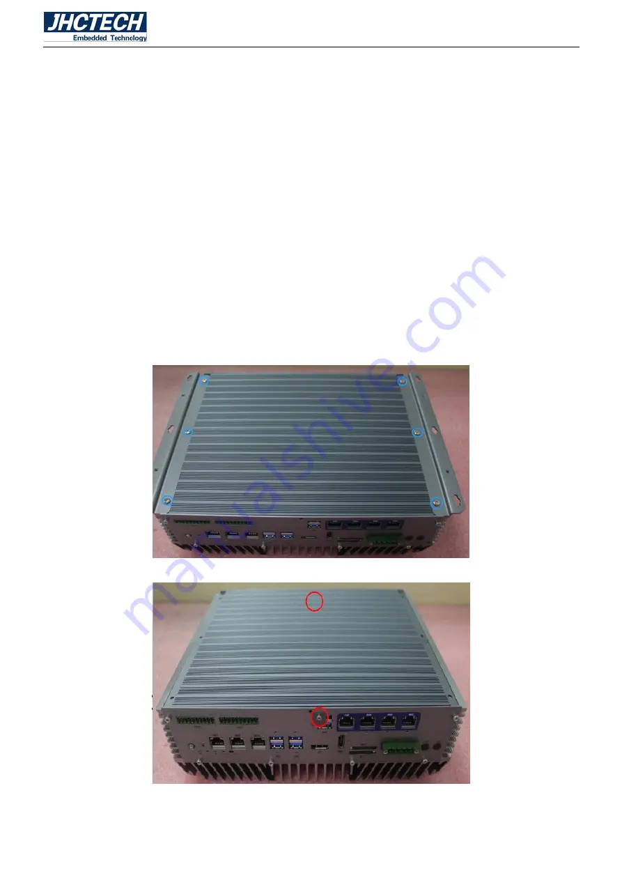
Step 1: Unscrew 6 screws on the underside, remove the bottom bracket;
Unscrew 2 screws on the front/rear panel;
Rotate the bottom assembly 180°, separate the SATA cable which connected the HDD/SSD with
the mother board;
Unscrew 7 screws and 10 serial copper columns on the rear panel, remove the rear panel;
Unscrew 6 screws on the front panel, remove the front panel;
Unscrew 2 screws of the internal USB;
Unscrew 2 screws on the sub-card ECB-148, remove the sub-card ECB-148;
Separate the POE power cable from the sub-card ECB-147;
Unscrew 2 screws and 2 serial copper columns on the sub-card ECB-147, remove the ECB-147;
Unscrew 4 screws on the HDD/SDD drive bay socket, remove the drive bay socket;
Summary of Contents for KMDA-3601
Page 1: ...User s Manual User s Manual KMDA 3601 Ver A1 0 Date 11 September 2018 ...
Page 2: ...User s Manual Version Note No Ver Note Date Writer 1 A1 0 first publish 20180911 Tracy Liu ...
Page 8: ...User s Manual 1 General Information CHAPTER 1 ...
Page 12: ...User s Manual 5 1 6 Mechanical Specifications Main Board Front AXM I950 Figure 1 0 Figure 1 1 ...
Page 14: ...User s Manual 7 Sub card ECB 148 Figure 1 5 Sub card ECB 149 Figure 1 6 ...
Page 15: ...User s Manual 8 KMDA 3601 Dimension Unit mm Figure 1 7 ...
Page 16: ...User s Manual 9 Hardware Installation CHAPTER 2 ...
Page 29: ...User s Manual 22 ...
Page 30: ...User s Manual 23 ...
Page 31: ...User s Manual 24 ...
Page 33: ...User s Manual 26 ...
Page 34: ...User s Manual 27 ...
Page 38: ...User s Manual 31 BIOS Setup CHAPTER 3 ...
Page 48: ...User s Manual 41 Driver Installation CHAPTER 4 ...


