background image


33

Subject 2: Suggestion on choosing electric fan 

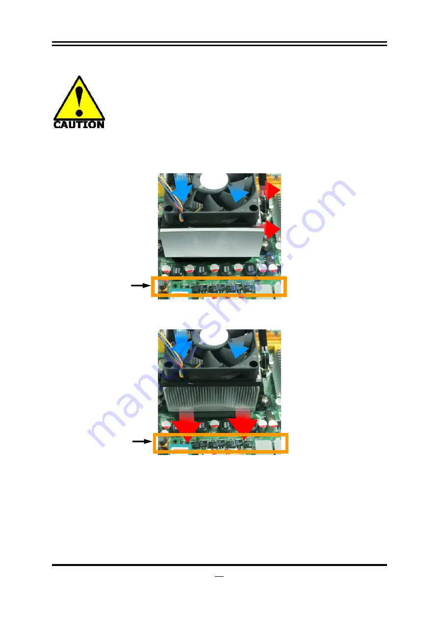
Both the amount of electric current to MOSFET and the heat produced 
from the motherboard go up as AMD’s CPU power consumption 
increases. In this case we recommend users select a CPU fan with air 
outlet towards MOSFET so that CPU fan can carry away heat 
produced by MOSFET, for better heat dissipation effects. At the same 

time we suggest using well-ventilated cases to maintain temperature as 38


approximately inside. (38

 is recommended by CPU manufactures)

.   


Figure 1----

 CPU Fan can not blow off the heat produced by MOSFET. We suggest 

not to using fans of this kind.


Figure 2----

 CPU Fan can blow off the heat produced by MOSFET. We suggest using 

fans of this kind. 


Cool air flowing in 

Hot air flowing out 

Cool air flowing in 

Hot air flowing out 

MOSFET 

MOSFET 

Summary of Contents for HA 18

Page 1: ...r Trademark Specifications and Information contained in this documentation are furnished for information use only and are subject to change at any time without notice and should not be construed as a...

Page 2: ...i Environmental Protection Announcement Do not dispose this electronic device into the trash while discarding To minimize pollution and ensure environment protection of mother earth please recycle...

Page 3: ...PROCEDURE FOR EXPANSION CARD INSTALLATION 10 2 5 3 INSTALLING CARD BRIDGE 11 2 6 CONNECTORS AND HEADERS 12 2 6 1 I O BACK PANEL CONNECTORS 12 2 6 2 INTERNAL CONNECTORS 13 2 6 3 INTERNAL HEADERS 14 CHA...

Page 4: ...it is moved from a cold environment to a warmer one to avoid condensation phenomenon These water drops attached on PCB or the surface of the components can bring about phenomena as minor as computer i...

Page 5: ...History Date 1 0 First Edition June 2011 Item Checklist 5 Motherboard 5 User s manual 5 DVD for motherboard utilities 5 SATA hard disk cable 5 I O Back Panel Shield Cooling Solutions for AMD Processor...

Page 6: ...2 PCI Express 2 0 x16 slot by 8 lane z 2 PCI Express 2 0 x1 slot z 1 32 bit PCI slot z 1 Mini PCIE slot SATA3 Ports z Supports six SATAIII devices providing 6 0 Gb sec data transfer rate and support R...

Page 7: ...ter and backward compatible with previous USB2 0 components SATA3 0 SATA3 0 6Gb s provides a higher bandwidth to retrieve and transfer HD media With this super speed data transfer SATA3 0 allows an in...

Page 8: ...ear or restore COMS settings by pressing down the button without taking trouble to remove the case and locate the jumper for clear CMOS Remove or turn off the power supply before COMS clear Other Feat...

Page 9: ...H HD Audio Connector POWER CAP USB 3 0 Ports 16MB Flash ROM 8 CH HD Audio Chip PCI Express 2 0 x1 RJ 45 Over USB 2 0 Ports G P I LED PS 2 Keyboard Port Optical S PDIF OUT Coaxial S PDIF_OUT Optical S...

Page 10: ...ault 8 Reboot 9 Install Operating System 10 Install Driver and Utility 2 2 Checking Motherboard s Jumper Setting 1 CMOS RAM Clear 3 pin JBAT1 A battery must be used to retain the motherboard configura...

Page 11: ...tting 2 3 Closed KB MS Power ON Enabled JP1 JP1 1 2 Closed KB MS Power ON Disable Default 3 3D Audio Function Select 3D_SW1 3D_SW1 3D_SW1 Pin1 3 Pin 2 4 Closed Nornal Pin1 Pin1 3D_SW1 Pin3 5 Pin4 6 Cl...

Page 12: ...e indicator of the CPU and make sure to install it matched with Pin 1 small triangle indicator of the CPU socket See to it that system is turned off and the installation direction is correct If the in...

Page 13: ...sure that the fastener of other side of the FAN clipped into another mounting lug on the opposite side of stand Then pull the level as to the right as the photo show above to fasten the fan 4 Insert p...

Page 14: ...les plug in either both DDRIII1 DDRIII2 or four DIMM Modules plug in DDRIII1 DDRIII4 2 Memory modules plugged in the same color DIMM must be of the same type same size and same frequency for dual chan...

Page 15: ...ty for the I O of peripherals 2 5 2 Procedure for Expansion Card Installation 1 Read the documentation for your expansion card and make any necessary hardware or software setting for your expansion ca...

Page 16: ...s with your VGA Cards 3 Be careful with the position for the pin you would like to set up 4 Keep straight to force the CF Bridges plug into both sides of CrossFire Tech Supported VGA Cards After the a...

Page 17: ...from CN5 CN1 UL1 The connectors are 4 pin USB 2 0 connectors to connect USB devices to the system board 6 LAN Port connector RJ 45 LAN port from UL1 This connector is standard RJ 45 LAN jack for Netw...

Page 18: ...s If you intend to use a PSU with 20 pin and 4 pin power plugs make sure that the 20 pin power plug can provide at least 15A on 12V and the power supply unit has a minimum power rating of 350W The sys...

Page 19: ...A3 Port connectors SATA1 SATA2 SATA3 SATA4 SATA5 SATA6 These SATAIII connectors support SATA 6Gb s specification Please connect SATAIII device to the connector with SATA cable One connector supports o...

Page 20: ...er SPEAK1 This 4 pin header connects to the case mounted speaker See the figure below 5 Power LED header PWR LED1 PWRLED The Power LED is light on while the system power is on Connect the Power LED fr...

Page 21: ...2 0 plugs affixed to the back panel USB Port Header Pin 1 VCC DATA GND DATA VCC OC DATA GND DATA 10 Serial COM Port header 9 PIN COM1 COM1 is a 9 pin RS232 connector Serial COM Port 9 pin Block Pin1 1...

Page 22: ...AN2 1 3 4 1 CPUFAN 12 Onboard Power LED The board has onboard LED indicators to show system running status More power LED on indicates heavier system workload More power LED off means system working i...

Page 23: ...communicate it is the key factor for system stability and in ensuring that your system performance as its best 3 1 Entering Setup Power on the computer and by pressing Del immediately allows you to en...

Page 24: ...is displayed at the top right corner the screen Status Page Setup Menu Option Page Setup Menu Press F1 to pop up a small help window that describes the appropriate keys to use and the possible selecti...

Page 25: ...guage Press to select the language for BIOS system System Date Set the date Please use TAB to switch between data elements System Time Set the date Please use TAB to switch between time elements 3 7 A...

Page 26: ...ernate OS S4 Sleep state This option may be not effective with some OS The optional settings Enabled Disabled ACPI Sleep State Use this item to select the highest ACPI sleep state the system will ente...

Page 27: ...7 2 S5 RTC Wake Settings Wake system with Fixed Time Use this item to enable or disable system wake on alarm event When set as Enabled system will wake on the hr min sec specified 3 7 3 SATA Configura...

Page 28: ...Transfer Time out Use this item to set the time out value for control bulk and interrupt transfer The optional settings are 1 sec 5 sec 10 sec 20 sec Device Reset Time Out Use this item to set USB mas...

Page 29: ...se this item to select an optimal setting for super IO device Wake up by PS 2 keyboard The optional settings are Disabled Enabled Wake up by PS 2 mouse The optional settings are Disabled Enabled EUP S...

Page 30: ...25 3 7 6 H W Monitor Press Enter to view PC health status 3 7 7 Shutdown Temperature Configuration Press Enter to set system shutdown temperature...

Page 31: ...enable or disable boot option for onboard network devices The optional settings are Enabled Disabled OnChip SATA Channel The optional settings are Enabled Disabled OnChip SATA Type The optional setti...

Page 32: ...his item to set number of seconds to wait for setup activation key Bootup Numlock State Use this item to select keyboard Numlock state The optional settings are On Off Boot Option 1 Use this item to s...

Page 33: ...to set PState limitation If the chosen value is larger than CPU support system will lock is on limit The optional settings are PState 0 Max PState 1 PState 2 PState 3 PState 4 Min C1E The optional se...

Page 34: ...this item to set memory clock mode The optional settings are Auto Specific When set as Specific the following sub item shall appear Memory Value The optional settings are DDR 667 333MHZ DDR 800 400MH...

Page 35: ...xxxx being the file name of the latest BIOS 4 Type Enter to update and flash the BIOS The system will restart automatically when BIOS is upgraded Solution2 Updating BIOS under Windows operating system...

Page 36: ...e click CD ROM drive or click START click RUN type X SETUP EXE assuming X is your CD ROM drive z Follow onscreen instructions to finish driver installation NOTICE The above driver screen and operation...

Page 37: ...han 65 W to ensure long term working order Note 1 The relation between CPU Power Consumption Amount and Power Phase depending on difference in voltage rating one phase of power can provide 25 30W to t...

Page 38: ...heat produced by MOSFET for better heat dissipation effects At the same time we suggest using well ventilated cases to maintain temperature as 38 approximately inside 38 is recommended by CPU manufact...

Reviews: