2
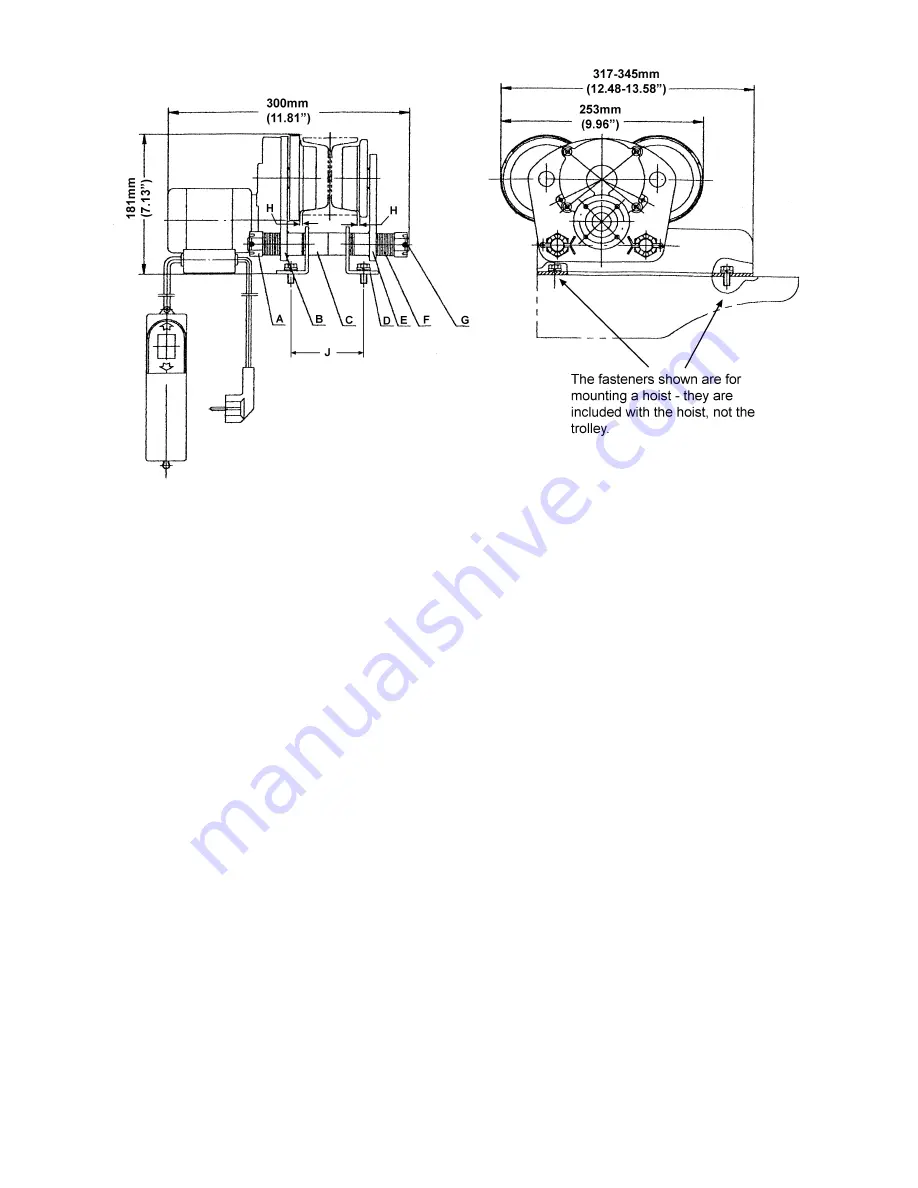
Figure 1
Installation and Adjustments
(refer to Figure 1)
Important: Use an assistant to help hold the trolley while you assemble it to the beam.
1. To adjust trolley width, remove split pins and slotted nuts (A) and slide out both shafts (G). Remove
washers (F) and collars (C) from shaft.
2. The trolley must be assembled to achieve two established measurements:
a. The trolley must be installed on a beam with a minimum clearance (wheels to flange) of 1/16”
to a maximum of 1/8” on each side of the beam. This clearance is shown as (H) in Figure 1.
Position the side plates (E) to achieve this measurement on your beam.
b. The angle irons (D) must be positioned so that the hole centerlines (J) match those of your
hoist. The angle irons should be evenly spaced from the side plates (E).
3. NOTE:
Washers
must be moved in sets of two, placing equal numbers on both sides to maintain the
centerline of the trolley.
4. Once the trolley width is spaced properly, install remaining washers on the bolt (same number on
both sides) on the outside of the side plates. Install slotted nuts and split pins. Do not over tighten
nuts. Tighten nuts, and then back nuts off as needed to clear the hole for the split pin. Insert split pin
through the hole in the shaft and bend down the ends of the split pin.
5. Double-check wheel clearance (H) and make further adjustments if necessary.
Replacement Parts
To order parts or reach our service department, call 1-800-274-6848 between 7:30 a.m. and 6:00 p.m.
(CST), Monday through Friday. Having the Model Number and Serial Number of your product available
when you call will allow us to serve you quickly and accurately.


