Jet JWL-1440VS Operating Instructions And Parts Manual Download Page 18


18

6.  Additional cuts may be taken to add to either 

the depth or width of the cut.   
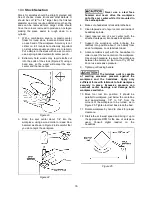
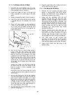
10.5.5

  Parting Off 

1.  Use parting tool. 

2.  Adjust lathe speed to lower RPM for parting 

through a workpiece. 

3.  Place tool on tool support and raise the handle 

until it starts to cut and continue to cut toward 
center of workpiece. 

4.  Loosely hold on to the piece in one hand as it 

separates from the waste wood. 
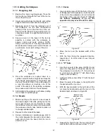
10.5.6

  Sanding and Finishing 

Leaving clean cuts will reduce the amount of 
sanding required. Move the tool support out of the 
way, adjust the lathe to a 

low speed

, and begin 

with fine sandpaper (120 grit or finer). Coarser 
sandpaper will leave deep scratches that are 
difficult to remove, and dull crisp details on the 
spindle. Progress through each grit without 
skipping grits (for example, do not jump from 120 
grit to 220 grit). Fold the sandpaper into a pad; do 
not wrap sandpaper around your fingers or the 
workpiece.To apply a finish, the workpiece can be 
left on the lathe.  

Turn off lathe and use a brush or paper towel to 
apply the finish. Remove excess finish before 
restarting lathe. Allow to dry and sand again with 
320 or 400 grit sandpaper. Apply second coat of 
finish and buff. 

10.6

  Face Plate and Bowl Turning 

Face plate turning is normally done on the inboard 
side of the headstock over the bed. Larger 
workpieces must be turned on the outboard side 
(remove tailstock and tool support base, and slide 
headstock to opposite end of bed). 
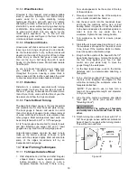
10.6.1

  Mounting Stock 

Use of a face plate is the most common method for 
holding a block of wood for turning bowls and 
plates: 

1.  Select stock at least 1/8" to 1/4" larger than 

each dimension on the finished workpiece. 

2.  Always select the largest diameter face plate 

that can be used for the workpiece to be 
turned. 

3. True one surface of the workpiece for 

mounting against the face plate. 

4.  Using the face plate as a template, mark the 

location of the mounting holes on the 
workpiece, and drill pilot holes of the 
appropriate size. Face plates are drilled for No. 
12 screws. (Phillips and square drive screws 
will hold up better than slotted screws. Sheel 

metal screws are case hardened with deeper 
and sharper threads than wood screws.) 

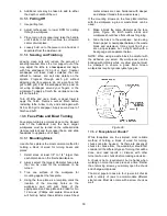
If the mounting screws on the face plate interfere 
with the workpiece, a glue or waste block can be 
used: 

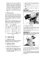
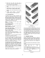
5.  Make a block the same diameter as the face 

plate, Figure 29. Both waste block and 
workpiece should have flat surfaces for gluing.  

6.  Glue the block to the workpiece. Avoid using 

brown paper or newspaper between the waste 
block and workpiece. It may work fine if you 
are using scrapers, but a slight catch with a 
bowl gouge can separate the two. 

NOTE: When using a waste block, be careful with 
the adhesive you select. Dry workpieces can be 
bonded with ordinary white or yellow glue but must 
be clamped to ensure a good bond. Green 
workpieces require cyanoacrylate type glue. 


Figure 29 

10.6.2

  Faceplate or Chuck? 

While faceplates are the simplest, most reliable 
method of holding a block of wood for turning, 
chucks can also be used.  As there are dozens of 
chucks to choose from, the woodturner should first 
consider all the different types of turning that will be 
done, and read reports or discuss with other 
turners who own chucks before making a decision.   

A chuck is not a requirement, but is handy when 
working on more than one piece at a time. Rather 
than removing screws, you simply open the chuck 
and change workpieces.  

The most popular ones are four jaw scroll chucks 
with a variety of jaws to accommodate different 
size tenons. Most also come with a screw chuck as 
well.  

Summary of Contents for JWL-1440VS

Page 1: ...nual 14 x 40 Woodturning Lathe Model JWL 1440VS JET 427 New Sanford Road LaVergne Tennessee 37086 Part No M 719400 Ph 800 274 6848 Revision C 11 2014 www jettools com Copyright 2014 JET Shown with opt...

Page 2: ...rvice Centers located throughout the United States For the name of an Authorized Service Center in your area call 1 800 274 6846 or use the Service Center Locator on the JET website More Information J...

Page 3: ...te Installing removing 13 8 13 Checking center alignment 14 9 0 Operating controls 14 10 0 Operation 14 10 1 Inspection 14 10 2 Turning Tools 15 10 3 Spindle Turning 15 10 4 Stock Selection 16 10 5 Cu...

Page 4: ...serious injury 17 Some dust created by power sanding sawing grinding drilling and other construction activities contain chemicals known to cause cancer birth defects or other reproductive harm Some e...

Page 5: ...or possible machine damage This means that if precautions are not heeded it may result in serious or possibly even fatal injury 4 0 About this manual This manual is provided by JET covering the safe o...

Page 6: ...national electrical codes Capacities Working distance between centers 40 1016mm Working distance between centers optional 20 bed ext mounted 60 3 4 1543mm Maximum distance between spindle face and ta...

Page 7: ...nsions assembled with Legs 74 L x 18 W x 49 H 1880 mm x 458mm x 1244mm Overall dimensions assembled without Legs 74 L x 18 W x 18 26 H 1880 mm x 458mm x 464mm Bed Extension length optional accessory 2...

Page 8: ...ome parts may have been pre installed If you did not purchase the leg set and are mounting the lathe to a bench or table continue with section 6 3 If you purchased the leg set skip to section 6 4 6 3...

Page 9: ...lower holes allows use of the tool support during outboard turning 1 Slide tailstock away from edge of bed 2 Have an assistant hold bed extension flush to end of lathe bed and insert four 3 8 socket...

Page 10: ...s are not completely understood or if in doubt as to whether the tool is properly grounded Failure to comply may cause serious or fatal injury Use only 3 wire extension cords that have 3 prong groundi...

Page 11: ...Push handle A Figure 9 toward motor to unlock Headstock will slide freely along the length of the bed Retighten handle before operating lathe 8 2 Headstock rotation 1 Loosen handle A Figure 9 2 Unscr...

Page 12: ...le H Figure 12 to raise or lower tool rest and angle it to the work Tighten handle before operating lathe Figure 12 8 6 Tool rest extension The extension J Figure 13 mounts to the tool rest base and o...

Page 13: ...connect lathe from power source 2 Clean the tapered end of the center and the inside of the tailstock quill then push the center into the quill Test the insertion by attempting to pull the center out...

Page 14: ...er minute in the adjoining window C Do not start lathe at maximum speed when a workpiece is mounted in the lathe Start at lower speed and gradually increase to desired speed Figure 20 The JWL 1440VS c...

Page 15: ...r sizing For safety and best performance keep tools sharp If a tool stops cutting or requires excessive pressure to make a cut it needs to be sharpened A number of brand name sharpening jigs and fixtu...

Page 16: ...ile it is mounted in the Lathe spindle 4 Make sure headstock is locked to lathe bed 5 Clean tapered end of spur center and inside of headstock spindle 6 Insert tapered end of spur center with the atta...

Page 17: ...th Place the parting tool on the tool support and move tool forward to make the full bevel of the tool come into contact with the workpiece Gently raise handle to make cut to the appropriate depth 2 R...

Page 18: ...argest diameter face plate that can be used for the workpiece to be turned 3 True one surface of the workpiece for mounting against the face plate 4 Using the face plate as a template mark the locatio...

Page 19: ...bowl gouges are only used for extremely large pieces Large domed scrapers can also be used to help clean up the interior surfaces of bowls A light touch with the scraper slightly tilted will eliminat...

Page 20: ...wall thickness at the rim and maintain it as you work deeper into the bowl Once the piece is thin toward the bottom you cannot make it thinner at the rim When the interior is finished move the tool s...

Page 21: ...and chips from accumulating on belts and sheaves Also blow off debris that accumulates in the motor fan Frequently clean out the morse tapers on both headstock and tailstock Commercially available tap...

Page 22: ...Replace spindle bearings Worn drive belt Replace drive belt Motor mount bolts are loose Tighten bolts Lathe on uneven surface Adjust leveling feet Tools tend to grab or dig in Dull tools Keep tools sh...

Page 23: ...ameter of workpiece Diameter of Work Roughing RPM General Cutting RPM Finishing RPM Under 2 1520 3000 3000 2 to 4 760 1600 2290 4 to 6 510 1080 1500 6 to 8 380 810 1125 8 to 10 300 650 900 10 to 12 25...

Page 24: ...mbination A 5 this will be followed by A 9 Succeeding flutes will be made with the index pin in the B position B 3 B 7 and so on No of Flutes 360 divided by Angle Letter Letter Letter 1 360 00 A 1 2 1...

Page 25: ...parts or reach our service department call 1 800 274 6848 Monday through Friday 8 00 a m to 5 00 p m CST Having the Model Number and Serial Number of your machine available when you call will allow us...

Page 26: ...21 Worm 1 26 JW1440 126 Control Panel 1 27 TS 081C052 Pan Head Screw 10 24 x 3 4 4 28 JWL1442 118 Switch 1 29 JWL1440 129 Pivot Pin Assembly includes 72 thru 77 1 30 JWL1442 127 Bushing 1 31 JWL1442 1...

Page 27: ...8071 Socket Head Cap Screw 5 16 18 x 1 1 4 2 65 JWL1440 165 Motor Cord 1 71 JWL1440 171 Key 1 72 JWL1440 172 Pivot Index Pin 1 73 JWL1442 175 Spring 1 74 JWL1442 176 Index Bushing 1 75 JWL1442 173 Ind...

Page 28: ...28 16 2 1 JWL 1440VS Bed Assembly Exploded View...

Page 29: ...nt for Live Center 1 16 JML 52 Live Center Head 1 17 BB 6002ZZ Ball Bearing 6002ZZ 1 18 JML 54 Live Center Shaft 1 JWL1440 TA Tailstock Assembly includes 19 thru 30 38 39 1 19 JWL1440 219 Quill MT 2 1...

Page 30: ...tion Size Qty 719402 JWL 1440VS Leg Set includes 1 thru 6 1 1 JWL1440 401 Leg 2 2 TS 0208071 Socket Head Cap Screw 5 16 18x1 1 4 8 3 TS 0720081 Lock Washer 5 16 8 4 TS 0680031 Flat Washer 5 16 8 5 JWL...

Page 31: ...PTIONAL Parts List Index No Part No Description Size Qty 719401 20 Extension Bed w Post includes 1 thru 6 1 1 JWL1440 301 Extension Bed 20 1 2 TS 0209071 Socket Head Cap Screw 3 8 16x1 1 2 4 3 TS 0720...

Page 32: ...32 17 0 Electrical Connections...

Reviews: