background image


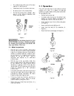
Place the selector switch on the handle in the 
center neutral position (Figure 6). Then grasp 
ring behind handwheel with one hand and 
rotate handwheel clockwise with other hand. 
This will allow free-wheel mode. (NOTE: Chain 
will only free-wheel when there is no load.) 
Take up slack by pulling on loose or free end of 
chain, or by turning handwheel. 


When finished with freewheel mode, rotate 
handwheel counterclockwise to re-engage 
lifting and lowering modes. 


Figure 6 


Move selector switch to the UP position. 
Ratchet the lever to raise or pull the load. Do 
not overload the lever hoist. 


To release or lower the load, turn selector 
switch on the handle to the DOWN position 
and ratchet the handle. 

Avoid lifting one load with two hoists. If this is 
unavoidable, apply equal weight to both hoists and 
use hoists with the proper lift capacity. 

Capacity of 

each

 hoist must be equal to the total load to be 

lifted. 

10.0

  Precautions 


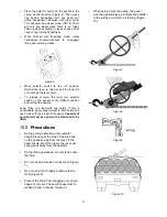
During pulling operations, the operator 
should stand near the side of the top hook 
on the opposite side from the lever. If the 
hand should slip off the lever, the lever will 
spring back away from the operator. 


During lifting operations, do not stand under 
the load. 


Do not use an extension on the lever (Figure 
7).  


Do not use a foot to apply pressure to the 
lever (Figure 8). 


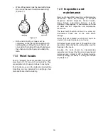
Prevent the chain from dragging over sharp 
edges or corners. These will cause links to 
weaken, bend, or break, (Figure 9). 


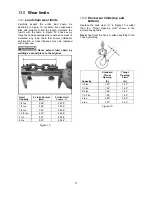
When using a wire rope sling, the puller 
must be applied along a straight line parallel 
to the surface on which it is resting (Figure 
10). 


Figure 7 


Figure 8 


Figure 9 


Figure 10 


Summary of Contents for JLP-A Series

Page 1: ...nual Lever Hoists Pullers 1 4 to 6 Ton models shown are representative of the series JET 427 New Sanford Road LaVergne Tennessee 37086 Part No M 187505 Ph 800 274 6848 Revision D2 07 2018 www jettools com Copyright 2018 JET JLP 150A 1 1 2 ton JLP 025A 1 4 ton ...

Page 2: ...n is twisted kinked or damaged 14 Do not operate hoist unless load is centered between top and bottom hooks 15 On hoists with the overload warning lever do not use this device to measure load weight 16 Always take time to study the job to be performed and choose the safest method Do not place yourself or other people in an unsafe position 17 Always maintain your balance and firm footing when opera...

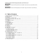
Page 3: ... Installation 7 8 0 Initial inspection 7 8 1 Inspecting the chain 7 8 2 Inspecting hooks 7 8 3 Other inspections 8 9 0 Operation 8 10 0 Precautions 9 11 0 Point hooks 10 12 0 Inspection and maintenance 10 13 0 Wear limits 11 13 1 Load chain wear limits 11 13 2 Hook wear limits top and bottom 11 13 3 Brake disc wear limits 12 14 0 Timing marks for gear replacement 12 15 0 Replacement parts 13 15 1 ...

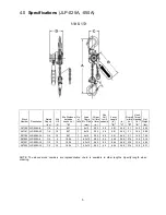
Page 4: ...owder coat finish and have a completely enclosed Weston type automatic brake system The JLP A series hoists are proof tested and comply with OSHA ANSI ASME B30 21 and HST 3 standards If there are any questions or comments please contact either your local supplier or JET JET can also be reached at our web site www jettools com The specifications in this manual were current at time of publication bu...

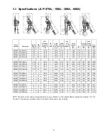
Page 5: ... 5 8 27 1 4x12 3 02 60 5 91 2 44 3 1 1 40 4 56 287101 JLP 025A 10 1 4 10 8 27 1 4x12 3 02 60 5 91 2 44 3 1 1 40 5 82 287102 JLP 025A 15 1 4 15 8 27 1 4x12 3 02 60 5 91 2 44 3 1 1 40 7 08 287200 JLP 050A 5 1 2 5 10 04 1 4 3x12 2 83 86 8 46 2 68 3 74 1 38 5 18 287201 JLP 050A 10 1 2 10 10 04 1 4 3x12 2 83 86 8 46 2 68 3 74 1 38 6 82 287202 JLP 050A 15 1 2 15 10 04 1 4 3x12 2 83 86 8 46 2 68 3 74 1 3...

Page 6: ... 67 287402 JLP 150A 15 1 1 2 15 14 96 1 8x24 0 87 49 16 14 6 37 7 03 1 85 34 33 287403 JLP 150A 20 1 1 2 20 14 96 1 8x24 0 87 49 16 14 6 37 7 03 1 85 39 02 287500 JLP 300A 5 3 5 18 89 1 10x30 0 69 71 16 14 8 21 7 66 2 46 42 65 287501 JLP 300A 10 3 10 18 89 1 10x30 0 69 71 16 14 8 21 7 66 2 46 49 97 287502 JLP 300A 15 3 15 18 89 1 10x30 0 69 71 16 14 8 21 7 66 2 46 57 25 287503 JLP 300A 20 3 20 18 ...

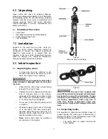
Page 7: ...he chain Check that the chain does not twist along its length from hoist to hook Replace the chain if links are stretched too long or seriously worn on the surface especially at the points where links contact each other See Allowable Limits on page 11 for measuring chain elongation Do not use a chain that is seriously rusted or cracked Periodically apply a light coat of 30 weight oil to the chain ...

Page 8: ...ndle travels before resistance or gearing is felt If free play has reached 3 4 of a turn brake discs are worn and should be replaced by a JET authorized service center The brake mechanism must be kept clean and free from dirt water and oil Never allow oil to penetrate the braking mechanism The brake should not slip while using the hoist If the lever hoist has not been used for an extended period o...

Page 9: ...le Avoid lifting one load with two hoists If this is unavoidable apply equal weight to both hoists and use hoists with the proper lift capacity Capacity of each hoist must be equal to the total load to be lifted 10 0 Precautions During pulling operations the operator should stand near the side of the top hook on the opposite side from the lever If the hand should slip off the lever the lever will ...

Page 10: ...Inspection and maintenance Read and follow ANSI Inspection and Maintenance Instructions Know the meaning of Frequent Inspection Periodic Inspection Normal Service Heavy Service and Severe Service It is the customer s responsibility to understand and follow all ANSI and JET inspection and maintenance instructions The lever hoist should be stored in a clean dry environment Clean and oil the hoist be...

Page 11: ...d chain by welding a second piece to the original Hoist Capacity 5 Links Normal mm 5 Links Limit Replace if 1 4 ton 2 36 2 433 1 2 ton 2 36 2 433 3 4 ton 3 54 3 629 1 1 2 ton 4 72 4 838 3 ton 5 91 6 058 6 ton 5 91 6 058 Figure 12 13 2 Hook wear limits top and bottom Replace the hook when A in Figure 13 is wider than the Throat Opening Limit shown in the accompanying table Never heat treat the hook...

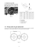
Page 12: ... 87 0 14 0 12 0 5 t 1 89 1 00 0 12 0 10 0 75 t 2 13 1 34 0 14 0 12 1 5 t 2 56 1 59 0 14 0 12 3 t 2 56 1 59 0 14 0 12 6 t 2 56 1 59 0 14 0 12 d Inner diameter D Outer diameter tn Normal measurement tv Replacement limit 14 0 Timing marks for gear replacement If the gears on the JLP A hoist need replacement or removal for any reason make sure they are re installed correctly Figure 16 shows the proper...

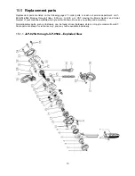
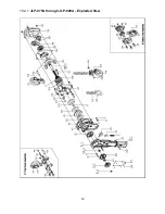
Page 13: ...to 5 00 p m CST Having the Model Number and Serial Number of your machine available when you call will allow us to serve you quickly and accurately Non proprietary parts such as fasteners can be found at local hardware stores or may be ordered from JET Some parts are shown for reference only and may not be available individually 15 1 1 JLP 025A through JLP 050A Exploded View ...

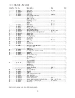
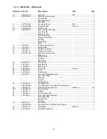
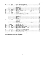
Page 14: ...m 1 18 JLP25A 18 Pawl 2 19 JLP25A 19 Pawl Spring 2 20 JLP25A 20 Brake Seat 1 21 JLP25A 21 Lever Side Plate Assembly 1 Lever Side Plate 1 Pawl Pin 1 22 JLP25A 22 Chain Guide 2 23 JLP25A 23 Load Sprocket and Pinion Shaft 1 24 JLP25A 24 Stay Bolt II 1 25 JLP25A 25 Spacer Pin 1 26 JLP25A 26G Top Hook Assembly 1 Top Hook 1 Top Hook Holder 2 Rivet 2 Top Hook Shaft 1 Safety Latch Kit 1 27 JLP25A 27 1 Saf...

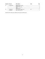
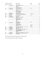
Page 15: ...y 38 JLP25A 38G Bottom Hook Assembly 1 Bottom Hook 1 Bottom Hook Holder 2 Rivet 2 Safety Latch Kit 1 39 JLP25A 39 Load Pin and Load Pin Nut M5 1 LM000048 Name Plate JLP 25A 1 Note All parts mentioned as assembly are sold as an assembly only ...

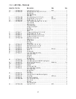
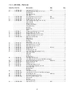
Page 16: ... 1 18 JLP25A 18 Pawl 2 19 JLP25A 19 Pawl Spring 2 20 JLP50A 20 Brake Seat 1 21 JLP50A 21 Lever Side Plate Assembly 1 Lever Side Plate 1 Pawl Pin 1 22 JLP50A 22 Chain Guide 2 23 JLP50A 23 Load Sprocket and Pinion Shaft 1 24 JLP50A 24 Stay Bolt II 1 25 JLP50A 25 Spacer Pin 1 26 JLP50A 26G Top Hook Assembly 1 Top Hook 1 Top Hook Holder 2 Rivet 2 Top Hook Shaft 1 Safety Latch Kit 1 27 JLP50A 27 1 Safe...

Page 17: ...y 38 JLP50A 38G Bottom Hook Assembly 1 Bottom Hook 1 Bottom Hook Holder 2 Rivet 2 Safety Latch Kit 1 39 JLP50A 39 Load Pin and Load Pin Nut M5 1 LM000049 Name Plate JLP 50A 1 Note All parts mentioned as assembly are sold as an assembly only ...

Page 18: ...18 15 2 1 JLP 075A through JLP 600A Exploded View ...

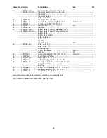
Page 19: ...Cover Assembly 1 Brake Cover 1 Handle Case 1 Bushing 1 Screw Nut 2 20 JLP75A 20 Friction Disc 2 21 JLP75A 21 Ratchet Disc 1 23 JLP75A 23 Brake Seat 1 24 JLP75A 24 Snap Ring Ø9 mm 2 25 JLP75A 25 Pawl 2 26 JLP75A 26 Pawl Spring 2 27 JLP75A 27 Lever Side Plate Assembly 1 Lever Side Plate 1 Stay Bolt 4 Pawl Pin 2 Bearing Race 1 28 JLP75A 28 Load Sprocket 1 JLP75A 28A Load Sprocket s n 120604733 and hi...

Page 20: ...ttom Hook 1 Bottom Hook Holder 2 Safety Latch Kit 1 Rivet 4 Load Pin 1 Load Pin Nut M6 1 63 JLP75A 63 1 Safety Latch Kit 2 Safety Latch 2 Double Spring 2 Socket Cap Screw M4x25 2 Lock Nut M4 2 64 JLP75A 64 Name Plate Rivet 0 75T 1 5T 3T 6T 3x6 mm 6 65 LM000050 Name Plate JLP 75A 1 66 1 JLP75A 66 1 Stop Knob 1 67 JLP75A 67 Twisting Spring 0 75T 1 5T 3T 6T 1 68 JLP75A 68 Hand Wheel Base Assembly 1 H...

Page 21: ... Cover 1 Handle Case 1 Bushing 1 Screw Nut 2 20 JLP150A 20 Friction Disc 1 5T 3T 6T 2 21 JLP150A 21 Ratchet Disc 1 5T 3T 6T 1 23 JLP150A 23 Brake Seat 1 5T 3T 6T 1 24 JLP150A 24 Snap Ring Ø9 mm 2 25 JLP150A 25 Pawl 2 26 JLP150A 26 Pawl Spring 2 27 JLP150A 27 Lever Side Plate Assembly 1 Lever Side Plate 1 Stay Bolt 4 Pawl Pin 2 Bearing Race 1 28 JLP150A 28 Load Sprocket 1 JLP150A 28A Load Sprocket ...

Page 22: ... 1 Bottom Hook Holder 2 Safety Latch Kit 1 Rivet 4 Load Pin 1 Load Pin Nut M8 1 63 JLP150A 63 1 Safety Latch Kit 2 Safety Latch 2 Double Spring 2 Socket Cap Screw M5x30 2 Lock Nut M5 2 64 JLP75A 64 Name Plate Rivet 0 75T 1 5T 3T 6T Ø3x6 mm 4 65 LM000051 Name Plate JLP 150A 1 66 1 JLP150A 66 1 Stop Knob 1 5T 3T 6T 1 67 JLP75A 67 Twisting Spring 0 75T 1 5T 3T 6T 1 68 JLP150A 68 Hand Wheel Base Assem...

Page 23: ... JLP150A 20 Friction Disc 1 5T 3T 6T 2 21 JLP150A 21 Ratchet Disc 1 5T 3T 6T 1 23 JLP150A 23 Brake Seat 1 5T 3T 6T 1 24 JLP300A 24 Snap Ring 3T 6T Ø9 mm 2 25 JLP300A 25 Pawl 3T 6T 2 26 JLP300A 26 Pawl Spring 3T 6T 2 27 JLP300A 27 Lever Side Plate Assembly 3T 6T 1 Lever Side Plate 1 Stay Bolt 4 Pawl Pin 2 Bearing Race 1 28 JLP300A 28 Load Sprocket 3T 6T 1 JLP300A 28A Load Sprocket 3T 6T s n 1204355...

Page 24: ... Bottom Hook Holder 2 Safety Latch Kit 1 Rivet 4 Load Pin 1 Load Pin Nut M10 1 63 JLP300A 63 1 Safety Latch Kit 2 Safety Latch 2 Double Spring 2 Socket Cap Screw M5x30 2 Lock Nut M5 2 64 JLP75A 64 Name Plate Rivet 0 75T 1 5T 3T 6T Ø3x6 mm 4 65 LM000052 Name Plate JLP 300A 1 66 1 JLP150A 66 1 Stop Knob 1 5T 3T 6T 1 67 JLP75A 67 Twisting Spring 0 75T 1 5T 3T 6T 1 68 JLP150A 68 Hand Wheel Base Assemb...

Page 25: ...0A 20 Friction Disc 1 5T 3T 6T 2 21 JLP150A 21 Ratchet Disc 1 5T 3T 6T 1 23 JLP150A 23 Brake Seat 1 5T 3T 6T 1 24 JLP300A 24 Snap Ring 3T 6T Ø9 mm 2 25 JLP300A 25 Pawl 3T 6T 2 26 JLP300A 26 Pawl Spring 3T 6T 2 27 JLP300A 27 Lever Side Plate Assembly 3T 6T 1 Lever Side Plate 1 Stay Bolt 4 Pawl Pin 2 Bearing Race 1 28 JLP300A 28 Load Sprocket 3T 6T 1 JLP300A 28A Load Sprocket 3T 6T s n 120615109 and...

Page 26: ... M10 3 55 JLP600A 55G Bolt A M10x30 2 56 JLP600A 56G Bolt B M8x25 1 57 JLP600A 57 Idle Shaft 1 58 JLP600A 58 Idle Sheave 1 60 F001755 Lock Nut M10 2 62 F001754 Lock Nut M8 1 63 1 JLP600A 63 1 Safety Latch Kit 2 Safety Latch 2 Double Spring 2 Socket Cap Screw M5x35 2 Lock Nut M5 2 64 JLP75A 64 Name Plate Rivet 0 75T 1 5T 3T 6T Ø3x6 mm 4 65 LM000053 Name Plate JLP 600A 1 66 1 JLP150A 66 1 Stop Knob ...

Page 27: ...needed JET has Authorized Service Centers located throughout the United States For the name of an Authorized Service Center in your area call 1 800 274 6846 or use the Service Center Locator on the JET website More Information JET is constantly adding new products For complete up to date product information check with your local distributor or visit the JET website How State Law Applies This warra...

Page 28: ...28 427 New Sanford Road LaVergne Tennessee 37086 Phone 800 274 6848 www jettools com ...

Reviews: