background image


14

Adjusting Blade Tracking 


  WARNING 

Blade tracking adjustment requires running 

the saw with the back cover open!  This 

adjustment must be completed by qualified 

persons only!   

Failure to comply may cause serious injury! 

 
Blade tracking has been set at the factory and 
should not need immediate adjustment.  If blade 
tracking should ever require adjustment: 
 
1.  Confirm that blade tension is set properly.  

To adjust, see section titled " Adjusting 
Blade Tension". 

 
2.  Make sure the saw is in its slowest speed, 

see “Changing Blade Speeds”. 

 
3.  Move saw arm to the vertical position and 

lock in place with the lock lever. 

 
4.  Confirm that blade tension is set properly.  

To adjust, see section titled " Adjusting 
Blade Tension". 

 
5.  Open blade cover by removing the knob 

found on the top side of the bow. 

 
6.  Run saw and observe blade.  Blade should 

run next to but not tightly against wheel 
flange. 

 
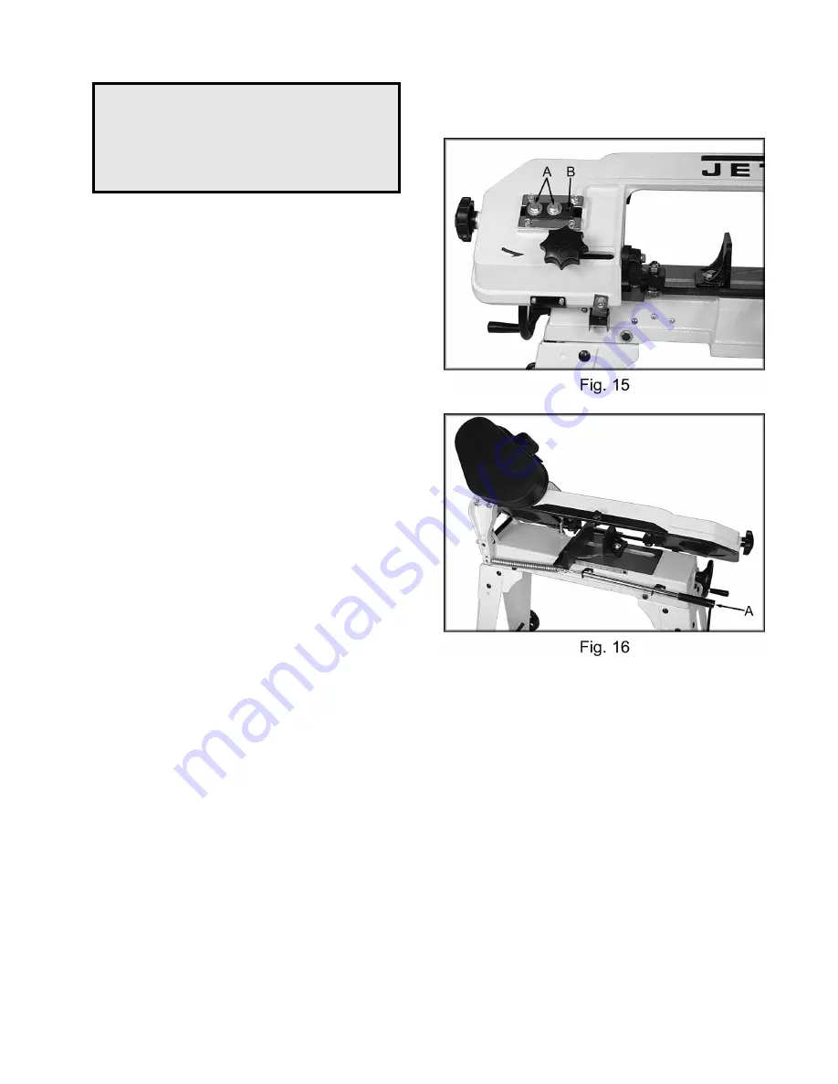
7.  Loosen bolts (A, Fig. 15). 
 
8.  Turn set screw (B, Fig. 15) while observing 

blade tracking on wheel.  Turn set screw 
clockwise to track closer to wheel flange.  
Turn set screw counter-clockwise to track 

away from the wheel flange.  

Hint:

  start 

with ¼ turns on the set screw.  The tracking 
is sensitive. 

 
9.  Once tracking is set, tighten bolts (A, Fig. 

15). 


Adjusting Feed Pressure 

 
1.  Turn handle (A, Fig. 16) clockwise to 

decrease cutting pressure and counter-
clockwise to increase cutting pressure. 

 
A good indication of proper feed pressure is the 
color and shape of the cutting chips.  If the chips 
are thin or powdered, increase the feed pressure.  
If the chips are burned and heavy, decrease the 

feed pressure.  If they are still burned and heavy, 
reduce the blade speed.  Optimum feed 
pressure has been set when the chips are curled, 
silvery, and warm. 
 

Summary of Contents for HVBS-56M

Page 1: ...l Horizontal Vertical Bandsaw Model HVBS 56M WALTER MEIER Manufacturing Inc 427 New Sanford Road LaVergne Tennessee 37086 Part No M 414458 Ph 800 274 6848 Revision G2 03 2010 www waltermeier com Copyright 2010 Walter Meier Manufacturing Inc ...

Page 2: ...age prepaid to a location designated by us For the name of the location nearest you please call 1 800 274 6848 You must provide proof of initial purchase date and an explanation of the complaint must accompany the merchandise If our inspection discloses a defect we will repair or replace the product or refund the purchase price at our option We will return the repaired product or replacement at ou...

Page 3: ...tting Plate Assembly 10 Electrical Connections 11 Changing Blade Speed 12 Adjusting Blade Guides 12 Adjusting Blade Tension 12 Changing Blades 13 Adjusting Blade Guide Bearings 13 Adjusting Blade Tracking 14 Adjusting Feed Pressure 14 Blade Table Squareness 15 Adjusting Automatic Shut Off 15 Adjusting the Vise 15 Lubrication 16 Breakdown for Bow Assembly 17 Breakdown for Base Assembly 18 Parts Lis...

Page 4: ...r extension cord is in good condition When using an extension cord be sure to use one heavy enough to carry the current your product will draw An undersized cord will cause a drop in voltage resulting in loss of power and overheating Table 1 shows the correct size to use depending on cord length and nameplate ampere rating If in double use the next heavier gage The smaller the gage number the heav...

Page 5: ...y affect its operation A guard or other part that is damaged should be properly repaired or replaced 21 Feed work into a blade or cutter only against the direction of rotation of the blade or cutter 22 Never leave tool running unattended Turn power off Don t leave tool until it comes to a complete stop 23 Give your work undivided attention Looking around carrying on a conversation and horse play a...

Page 6: ... grounded Use only three wire extension cords that have three prong grounding plugs and three pole receptacles that accept the tool s plug Repair or replace a damaged or worn cord immediately This tool is intended for use on a circuit that has an outlet that looks like the one illustrated in sketch A The tool has a grounding that looks like the plug illustrated in sketch A A temporary adapter whic...

Page 7: ...ivels 45 Blade Size 1 2 x 0 025 x 64 1 2 Blade Wheel Diameter 7 3 8 Speeds 80 120 200 SFPM Bed Height 25 1 2 Floor Space Required 16 1 4 x 42 1 2 Motor UL listed 1 2 HP 1 Ph 115 230V prewired 115V Net Weight approx 115 lbs The specifications in this manual are given as general information and are not binding Walter Meier Manufacturing Inc reserves the right to effect at any time and without prior ...

Page 8: ...nch Set Pliers Regular or Needle Nose Ratchet and Sockets will Speed Assembly Assembly 1 With the help of another person turn the saw over so that it rests on the motor and saw bow Figure 1 Place it on a piece of cardboard or a surface that will not damage the saw 2 Attach a cross brace A Fig 1 to the motor side of the bed using three 5 16 x1 hex cap bolts six 5 16 flat washers and secure with thr...

Page 9: ...r 5 16 hex nuts Use a 12mm wrench to tighten Repeat for other leg 7 Attach the adjustable feet A Fig 2 to the legs opposite of the motor using the provided hardware 8 Slide the axle A Fig 3 through the legs Place a large flat washer B Fig 3 on both sides of the wheels and place on the axle Secure wheels with two split pins C Fig 3 9 Carefully turn the saw onto its stand and adjust the feet so the ...

Page 10: ... the two pulleys causes approximately 1 2 deflection Close pulley cover Don t over tighten the belt 16 Insert stop rod A Fig 6 into bed and tighten set screw B Fig 6 Slide stock stop C Fig 6 onto rod and tighten set screw D Fig 6 to hold in place 17 Slide handwheel E Fig 6 onto shaft and secure by tightening set screw F Fig 6 Make sure set screw seats on flat portion of shaft Vertical Cutting Plat...

Page 11: ... the wiring diagram found on the inside of the motor junction box The plug on the end will have to be replaced with a plug that is rated at 230V This bandsaw is designed for use on a circuit with an outlet that looks like A Fig 9 The bandsaw has a grounding prong as illustrated in B Fig 9 A temporary adapter C Fig 9 may be used to connect the plug to a two pole receptacle D Fig 9 if a properly gro...

Page 12: ... Disconnect machine from the power source 2 Loosen knob A Fig 12 and slide blade guide assembly B Fig 12 as close as possible without interference to the material being cut Tighten knob 3 Loosen bolt C Fig 12 and slide blade guide assembly D Fig 12 as close as possible without interference to the material being cut Tighten bolt Adjusting Blade Tension 1 Disconnect machine from the power source 2 O...

Page 13: ...ards with two screws 8 Tension blade fully see Adjusting Blade Tension 9 Place two to three drops of lightweight oil on the blade 10 Connect machine to the power source 11 Run saw and make sure blade is tracking properly see Adjusting Blade Tracking As a general rule the thinner the material to be cut the more teeth per inch on the blade A minimum of three teeth should be in contact with the mater...

Page 14: ...b found on the top side of the bow 6 Run saw and observe blade Blade should run next to but not tightly against wheel flange 7 Loosen bolts A Fig 15 8 Turn set screw B Fig 15 while observing blade tracking on wheel Turn set screw clockwise to track closer to wheel flange Turn set screw counter clockwise to track away from the wheel flange Hint start with turns on the set screw The tracking is sens...

Page 15: ... blade adjustments as noted in your manual Adjusting Automatic Shut Off The saw should stop after the cut has been completed If the saw completes the cut and continues to run adjust the stop tip A Fig 17 down If the saw shuts off before the cut is complete adjust the stop tip A Fig 17 up If the saw stops cutting but continues to run adjust the stop bolt B fig 17 down The saw is properly adjusted w...

Page 16: ...gear box oil 1 Disconnect machine from the power source 2 Place saw arm in the horizontal position 3 Remove screws A Fig 18 from the gear box and remove cover plate and gasket 4 Hold a container under the lower right corner of the gear box with one hand while slowly raising the saw arm with the other Drain completely 5 Place arm in the horizontal position Wipe out remaining oil with a rag 6 Fill g...

Page 17: ...17 Breakdown for Bow Assembly ...

Page 18: ...18 Breakdown for Base Assembly ...

Page 19: ... Socket Set Screw 5 16 x5 16 4 21 HVBS462 021 Stock Stop Rod 1 22 HVBS462 022 Wire Relief Retainer 2 25 TS 0051031 Hex Cap Bolt 5 16 x3 4 1 27 HVBS462 027 Wheel Handle 1 28 HVBS462 028 Hand Wheel 1 29 HVBS56M 029 Toggle Switch Assembly 1 29 1 HVBS56M 029 1 Plastic Cover 1 30 HVBS462 030 E Ring E10 1 31 HVBS462 031 Screw 5 16 x1 3 32 HVBS462 032 Lead Screw 1 33 HVBS462 033 Vise Nut 1 34 HVBS462 034...

Page 20: ...able Bracket RH 1 65A HVBS56M 065A Adjustable Bracket Assembly RH 1 66 HVBS56M 066 Lock Knob 1 67 TS 0720081 Lock Washer 5 16 3 68 TS 0813051 Flat Head Machine Screw 1 4 X3 4 3 69 HVBS462 069 Bearing Guard 1 70 TS 0561031 Hex Nut 3 8 4 71 HVBS462 071 Blade Wheel Drive 1 72 HVBS462 072 Bearing Cover 2 73 HVBS462 073 Key 5x5x25 2 74 HVBS56M 060 C Clip S15 1 75 HVBS462 075 Hex Cap Bolt w Washer 1 4 x...

Page 21: ...ding Guide 2 110 HVBS462 110 Motor Pulley Cover Assembly 1 111 TS 0680031 Flat Washer 5 16 1 112 VB A22 V Belt A22 1 113 414301 Blade 1 114 TS 0680041 Flat Washer 3 8 4 115 TS 0561011 Hex Nut 1 4 1 116 HVBS463 170 Wire Plug 3 117 HVBS463 171 Hex Screw 3 8 x1 1 4 1 120 HVBS462 120 Bushing 1 122 TS 0561041 Hex Nut 7 16 1 123 TS 0050031 Cap Screw 1 4 x3 4 1 124 HVBS463 124 Machine Screw 3 16 x3 4 2 1...

Page 22: ...22 Wiring Diagram ...

Page 23: ...23 Notes ...

Page 24: ...24 WALTER MEIER Manufacturing Inc 427 New Sanford Road LaVergne Tennessee 37086 Phone 800 274 6848 www waltermeier com ...

Reviews: