


12
7.0
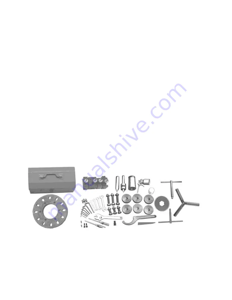
Unpacking
Open shipping container and check for shipping
damage. Report any damage immediately to your
distributor and shipping agent. Do not discard any
shipping material until the Lathe
is assembled and
running properly.
Compare the contents of your container with the
following parts list to make sure all parts are intact.
Missing parts, if any, should be reported to your
distributor. Read the instruction manual thoroughly
for assembly, maintenance and safety instructions.
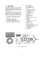
7.1
Contents of shipping container
1 Lathe
1
Steady Rest (mounted on Lathe)
1
Follow Rest (mounted on Lathe)
1
10” Three Jaw Chuck (mounted on Lathe)
1
Face Plate (12” Face Plate for 14” & 16”
lathes; 16” Face Plate for 18” & 22” lathes)
1 Tool Box containing:
1
Open
End
Wrench
Set
1
Hex
Wrench
Set
1
Morse
Reduction
Sleeve
1
Center
6
Leveling Bolts with Hex Nuts
2 Hex Screws with Washers
6
Leveling
Pads
1
Flat
Blade
Screwdriver
1
Cross
Point
Screwdriver
1
Chuck
Wrench
1
Cam
Wrench
1
Adjustable
Wrench
1
Round
Nut
Wrench
1
Oil
Gun
1
Cross Feed Handle (not shown)
2
Shear
Pins
1 Paint Can
4 Tool Holder
3 Sliding Sleeve
(
for 14” lathes
)
1 Indicate Bulb
1 Key for Cam Locks
1 Gear
1
Gap Bridge Pin Driver
1
Live Center (MT4 for 14” & 16” lathes;
MT5 for 18” & 22” lathes)
1
Operating
Instructions
Manual
1
Parts List Manual
1
Test
Record
1
Warranty
Card
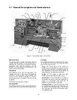
Figure 3 - Contents of tool box
Summary of Contents for GH-1440ZX
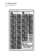
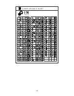
Page 26: ...26 T H R E A D I N G C H A R T I N I N C H ...
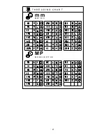
Page 27: ...27 m m M E T R I C T H R E A D I N G C H A R T M P M O D U L E P I T C H ...
Page 31: ...3 1 1 Stand Assembly Exploded View ...
Page 34: ...6 2 1 Brake Assembly Exploded View ...
Page 36: ...8 3 1 Bed Assembly Exploded View ...
Page 39: ...11 4 1 Headstock Assembly I Exploded View ...
Page 43: ...15 5 1 Headstock Assembly II Exploded View ...
Page 46: ...18 6 1 Headstock Assembly III Exploded View ...
Page 48: ...20 7 1 Headstock Assembly IV Exploded View ...
Page 50: ...22 8 1 Change Gear Box Assembly I Exploded View ...
Page 52: ...24 9 1 Change Gear Box Assembly II Exploded View ...
Page 54: ...26 10 1 Quick Change Gear Box I Exploded View ...
Page 57: ...29 11 1 Quick Change Gear Box II Exploded View ...
Page 59: ...31 12 1 Quick Change Gear Box III Exploded View ...
Page 61: ...33 13 1 Apron Assembly I Exploded View ...
Page 64: ...36 14 1 Apron Assembly II Exploded View ...
Page 67: ...39 15 1 Apron Assembly III Exploded View ...
Page 69: ...41 16 1 Carriage Assembly Exploded View ...
Page 73: ...45 18 1 Carriage Stop Assembly Exploded View ...
Page 75: ...47 19 1 Quick Change Tool Post Exploded View ...
Page 77: ...49 20 1 Tailstock Assembly I Exploded View ...
Page 79: ...51 21 1 Tailstock Assembly II Exploded View ...
Page 81: ...53 22 1 Steady Rest Assembly Exploded View ...
Page 83: ...55 23 1 Follow Rest Assembly Exploded View ...
Page 85: ...57 24 1 Coolant Work Light Assembly Exploded View ...
Page 89: ...61 26 2 Electrical Cabinet Breakdown 6 7 8 12 11 10 17 22 21 23 13 9 9a 20 18 3a 1 2 4 19 3 ...
Page 90: ...62 27 0 Wiring Diagram ...
Page 94: ...66 427 New Sanford Road LaVergne Tennessee 37086 Phone 800 274 6848 www jettools com ...


