14
11.
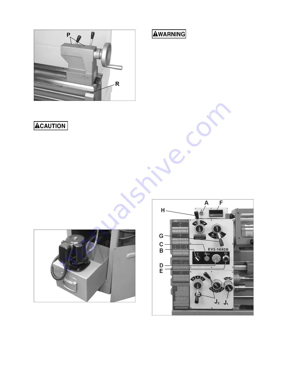
Leadscrew
– Lubricate ball oiler (R, Figure 7-
6) once daily.
Figure 7-6
7.1
Coolant preparation
Follow local regulations and/or
coolant manufacturer’s recommendations for
use, care and disposal.
1. Remove access cover at rear of stand near
tailstock end, and pull out coolant tank. See
Figure 7-7.
2. Pour approximately 9 liters (2.38 gal.) of coolant
mix into reservoir.
3. After machine has been connected to power,
turn on coolant pump and check to see that
coolant is cycling properly. Flow is controlled by
the tap at the base of the nozzle.
4. Replace coolant assembly into its chamber, and
reinstall access cover.
To change coolant, pull out coolant tank and dump
dirty coolant. Clean the tank of any chips or residue.
Refill with proper amount of new coolant.
Figure7-7
8.0
Electrical connections
Electrical connections must be
made by a qualified electrician in compliance
with all relevant codes. This machine must be
properly grounded while in use to help protect
the operator from electrical shock and possible
fatal injury.
The lathe is rated for
230 volt, 3-phase incoming
power.
Confirm that power available at the lathe’s
location is the same rating as the lathe.
IMPORTANT:
The lathe must be wired properly and
phased correctly. The spindle should rotate
counterclockwise (as viewed from tailstock end)
while the feed rod rotates clockwise (as viewed from
tailstock end). If the phasing needs correction,
disconnect lathe from power source and switch any
two of the three power leads (not the green ground
wire).
The inverter will accept 3-phase or single-phase
input. If wiring for single phase input, connect at R
and T, as shown in the wiring diagram in
sect. 16.0.
Make sure lathe is properly grounded.
Chuck should rotate counterclockwise, as viewed
from tailstock, when spindle direction control lever
(see O, Figure 9-2) is in down position. If rotation is
opposite, disconnect power and switch any 2 of the
power supply wires to the junction box.
9.0
Controls
Figure 9-1
1.
Control Panel:
Located on front of headstock.
Summary of Contents for EVS-1440B
Page 9: ...9 5 1 Machine dimensions and hole spacing Figure 5 1 Figure 5 2 ...
Page 23: ...23 13 0 Thread and feed chart Table 9 ...
Page 26: ...26 15 1 2 EVS 1440B Headstock Assembly Exploded View II ...
Page 27: ...27 15 1 3 EVS 1440B Headstock Assembly Exploded View III ...
Page 30: ...30 15 2 1 EVS 1440B Gearbox Assembly Exploded View I ...
Page 31: ...31 15 2 2 EVS 1440B Gearbox Assembly Exploded View II ...
Page 32: ...32 15 2 3 EVS 1440B Gearbox Assembly Exploded View III ...
Page 35: ...35 15 3 1 EVS 1440B Apron Assembly Exploded View I ...
Page 36: ...36 15 3 2 EVS 1440B Apron Assembly Exploded View II ...
Page 37: ...37 15 3 3 EVS 1440B Apron Assembly Exploded View III ...
Page 40: ...40 15 4 1 EVS 1440B Carriage Assembly Exploded View ...
Page 42: ...42 15 5 1 EVS 1440B Tool Post Assembly Exploded View ...
Page 44: ...44 15 6 1 EVS 1440B Tailstock Assembly Exploded View ...
Page 46: ...46 15 7 1 EVS 1440B Bed Assembly Exploded View ...
Page 48: ...48 15 8 1 EVS 1440B Cabinet and Panel Assembly Exploded View ...
Page 50: ...50 15 9 1 EVS 1440B End Gear Assembly Exploded View ...
Page 60: ...60 15 19 1 892035 Taper Attachment Assembly OPTIONAL Exploded View ...
Page 62: ...62 15 20 1 EVS 1440B Control Plate Assembly Exploded View ...
Page 64: ...64 16 0 Electrical Connections for EVS 1440B ...
Page 65: ...65 ...
Page 66: ...66 ...
Page 68: ...68 427 New Sanford Road LaVergne Tennessee 37086 Phone 800 274 6848 www jettools com ...


