11
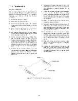
Align infeed table with sander’s conveyor table as
follows.
See Figures 6-3 and 6-4.
6. Place a straight-edge at one side of conveyor
table under drum and extending out over infeed
table. See Figure 6-4. You may wish to lower
drum until it contacts the straight edge to hold it
in place.
7. Raise infeed table until it evenly contacts
straight edge. If needed, loosen four screws
(HP4) beneath table and adjust table to level.
Tighten screws.
8. Loosen screw (HP6) and rotate eccentric cam
(HP8) until it contacts lip of table bracket. Do
this on both sides of infeed table. This ensures
infeed table will remain level with conveyor
table each time it is returned to operating
position. Tighten screws (HP6).
9. Install outfeed table using identical procedure
as above.
TIP: It is often preferable to position infeed/ outfeed
tables
slightly below
conveyor table surface,
particularly if stock being sanded is bowed, warped
or otherwise inconsistent. Also, if stock slips on
conveyor, the tables may be positioned too high.
Figure 6-4: infeed table alignment
6.7
Dust collection
Dust collection is mandatory for a safe work
environment and extended abrasive life. The
JWDS-2244/2550 is equipped with a 4-inch dust
collection port. Secure a 4-inch dust collection hose
to the port with a hose clamp (Figure 6-5), and
connect to a high volume dust collector (minimum
550 CFM).
Note: Dryer vent hose is not acceptable
for this purpose.
Keep hose clear of conveyor area by directing it over
the hose hanger at rear of sanding head.
A standard shop type canister (16 gal. or larger) can
be used for short periods of sanding time but
requires converting the hose size down to 2-1/2
inch. An adaptor (not included) is required.
Figure 6-5 (hose and clamp not included)
6.8
Installing abrasives
Proper attachment of the abrasive strip to the drum
is critical to achieving top performance from your
drum sander.
An 80-grit, 3-inch wide abrasive is pre-installed on
drum. Optional pre-cut (“Ready-to-Wrap”) abrasives
of different grits are available; see
sect. 14.0
.
(TIP: If you are using an after-market abrasive, use
a new JET-supplied abrasive as a template to
quickly cut a new strip. Alternatively, a diagram is
supplied in Figure 6-6 showing trim dimensions.)
Figure 6-6: abrasive trimming
(not applicable to Ready-to-Wrap strips)
To install abrasive strip:
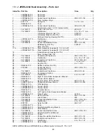
1. Press fastener lever (Figure 6-7) on outboard
(left) end of drum, and insert tapered end of
abrasive through slit in fastener, as shown.
Align tapered edge of abrasive strip with left
edge of drum. Insert enough strip so that the
right edge aligns with the reference notch; this
will ensure the proper length of strip to be
secured at the opposite end of the drum.
Figure 6-7


