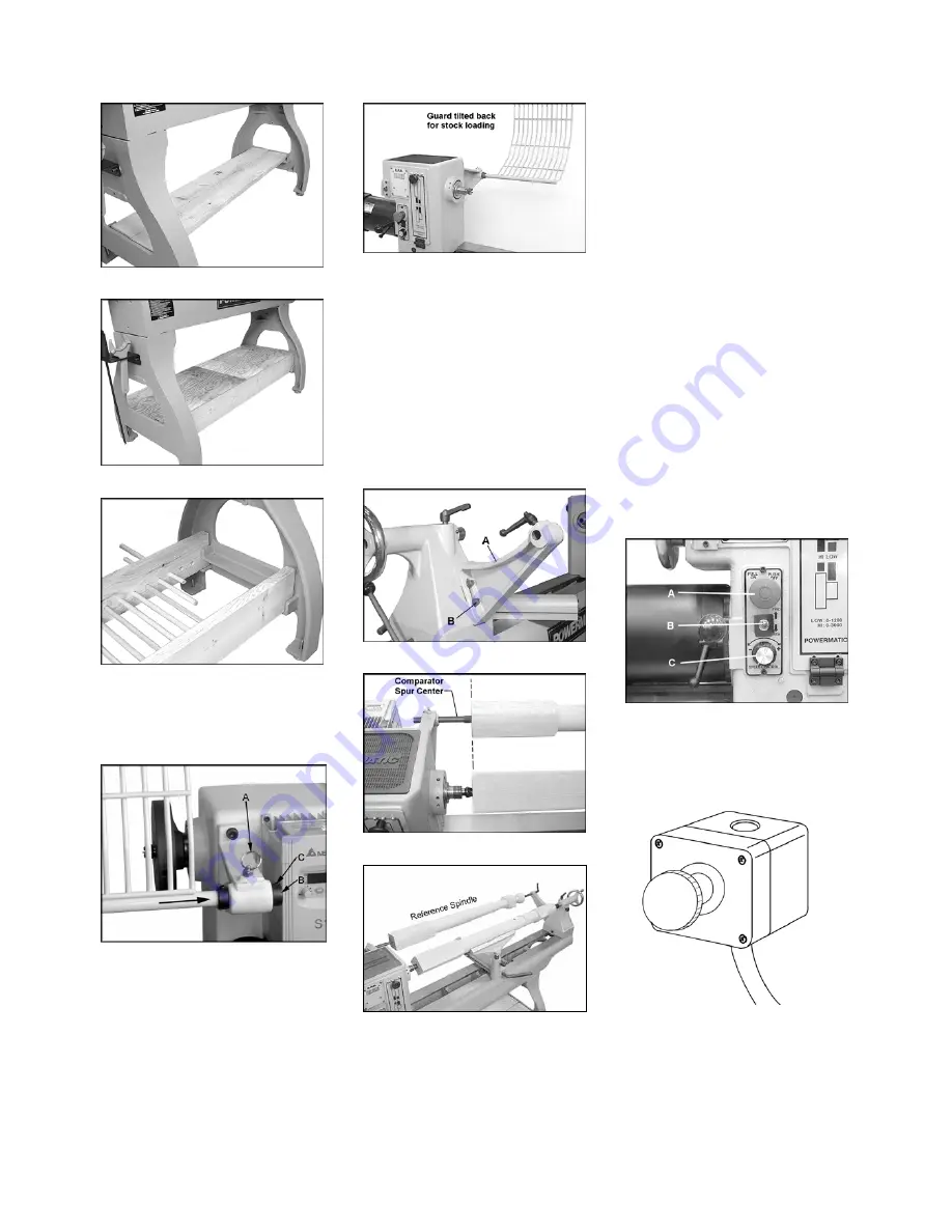
Fig 5
Fig 6
Fig 7
Guard assembly:
Attach guard to the bracket by
inserting the rod and lifting up on the
plunger (A, Fig 8).
Fig 8
There are two detents that will hold the
guard in place.
One is for turning and the other is for
when you need the guard up and out
of the way.
Tighten the bushings (B) against the
bracket with two set screws (C).
Fig 9
Optical comparator assembly:
Mount the comparator rear bracket (A,
Fig 10) to the back of the tailstock with
two socket head cap screws, lock
washers and washers (B).
The bracket has a slot so it can be
aligned with the bracket on the
headstock.
The comparator allows to hold a
sample workpiece for optical reference
and comparative measurement taking.
( see Fig 11-12).
Fig 10
Fig 11
Fig 12
5.3 Mains connection
Mains connection and any extension
cords used must comply with
applicable regulations.
The mains voltage must comply with
the information on the machine licence
plate.
The mains connection must have a
16 A surge-proof fuse.
Only use power cords marked H07RN-
F
Connections and repairs to the
electrical equipment may only be
carried out by qualified electricians.
5.4 Dust collection
Use a suitable dust collection and
filtration system to avoid a high dust
concentrations in the air.
5.5 Starting operation
You can start the machine by pulling
the red ON/OFF button (A, Fig 13).
Fig 13
The machine will stop when you push
the red ON/OFF button (A, Fig 13) or
the remote control ON/OFF button (Fig
14).
Fig 14
Turn the knob (C) to the desired RPM.
There are 2 speed ranges offering
“speed” (0-3200 rpm) and
“torque” (0-1200 rpm).


