background image

JMS7010

3

INSTALLATION

This unit is designed for installation in vessels with an existing standard size DIN radio 
opening. 

Before You Begin

1.

Disconnect Battery

Before you begin, always disconnect the battery negative terminal.

2.

Remove Transport Screw

Please remove the shipping screw before installation. If the screw is left in place, the CD 
mechanism will not operate.

Important Notes

Before final installation, test the wiring connections to make sure the unit is connected 
properly and the system works.

Use only the parts included with the unit to ensure proper installation. The use of 
unauthorized parts can cause malfunctions.

Consult with your nearest dealer if installation requires the drilling of holes or other 
modifications to your vessel.

Install the unit where it does not interfere with steering and cannot injure passengers if 
there is a sudden or emergency stop or sharp turn.

Avoid installing the unit where it will be subject to high temperatures from direct sunlight 
or hot air, or where it would be subject to excessive dust, dirt or vibration.

Install the unit within 30° of the horizontal plane.

DIN Front Mount

1.

Check the dashboard opening size by sliding the radio into it. If the opening is not large 
enough, carefully cut or file as necessary until the radio easily slides into the opening. 
Check that there will be sufficient space behind the dashboard for the radio chassis. Use 
the included drilling template to prepare the opening on a new mounting surface.

2.

Place the radio in front of the dashboard opening so the wiring can be brought through the 
DIN opening.

3.

Follow the wiring diagram carefully and make certain all connections are secure and 
insulated with crimp connectors or electrical tape to ensure proper operation. 

4.

After completing the wiring connections, turn the unit on to confirm operation (vessel 
accessory switch must be on). If the unit does not operate, recheck all wiring until the 
problem is corrected. Once proper operation is achieved, turn the accessory switch off 
and proceed with final mounting of the chassis.

5.

Carefully slide the radio into the dashboard making sure it is right-side-up.

6.

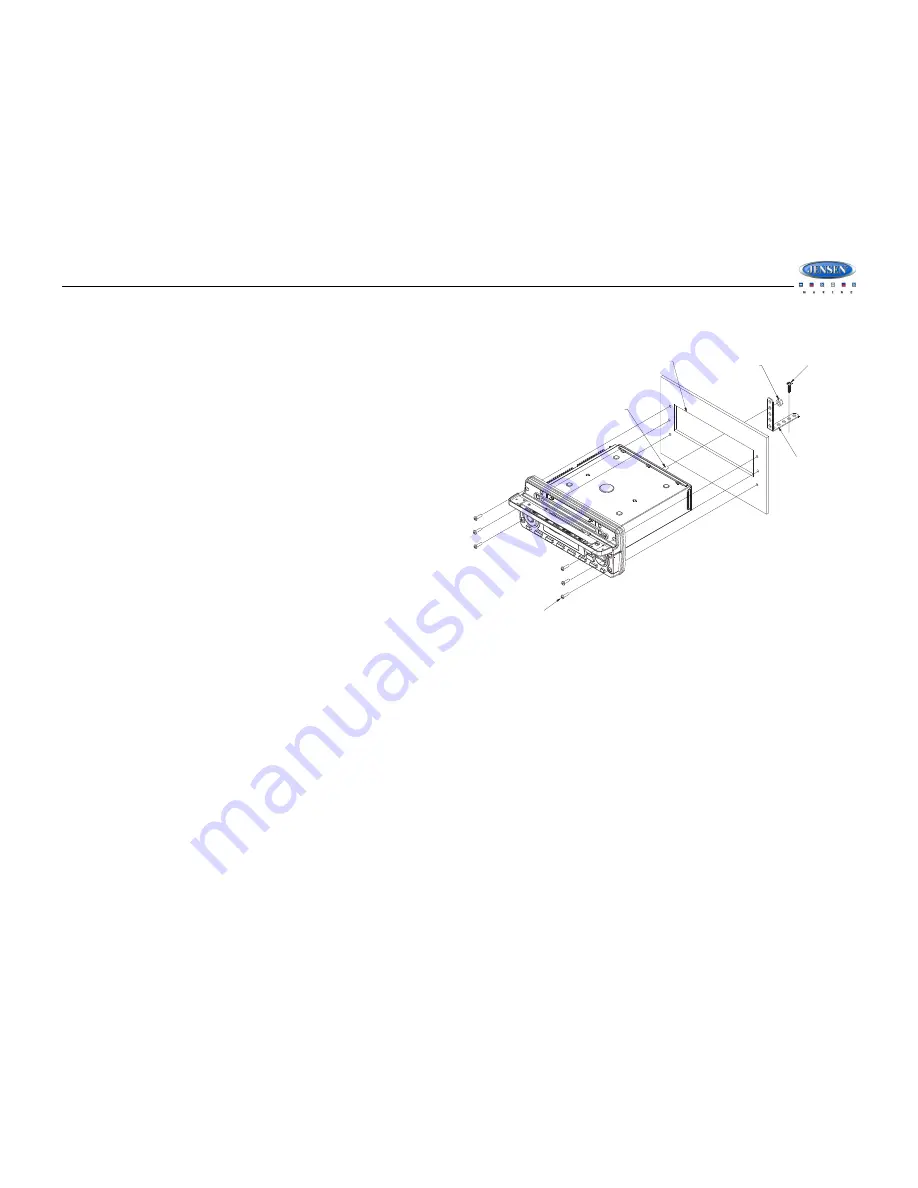
Attach one end of the Perforated Support Strap (supplied) to the Rear Support Stud on 
the rear of the chassis using the M5 Mounting Nut provided. Fasten the other end of the 
perforated strap to a secure part of the dashboard either above or below the radio using 
the screw and plain washer provided. Bend the strap, as necessary, to position it. 

CAUTION: The perforated rear support strap must be used in the installation of the 
radio. Installation without the strap may result in damage to the radio or the 
mounting surface and void the manufacturer’s warranty

.

7.

Install the six #6 Stainless Steel Mounting Screws through the front of the radio into the 
dashboard. 

CAUTION: Radio must be secured using all 6 mounting points. Failure to do so may 
result in damage to the radio or dashboard.

8.

Test radio operation by referring to the operating instructions for the unit.

Reconnect Battery

When wiring is complete, reconnect the battery negative terminal.

#6 ROUND HEAD STAINLESS STEEL

MOUNTING SCREW (6-PLCS.)

MINIMUM SCREW LENGTH 1 1/2"

STANDARD SIZE DIN

REAR SUPPORT STUD

M5 MOUNTING NUT

PERFORATED REAR
SUPPORT STRAP

USED TO SECURE TO
SUB DASH STRUCTURE

Summary of Contents for JMS7010

Page 1: ...JMS7010 Installation and Operation Manual Waterproof AM FM RBDS WB CDP Sirius iPod Ready Marine Radio ...

Page 2: ...em Features 1 Safety Information 2 Installation 3 Wiring 4 Basic Operation 5 Tuner Operation 8 CD MP3 USB Playback 10 Satellite Radio Operation 11 iPod Operation 13 Care and Maintenance 15 Troubleshooting 15 Specifications 16 ...

Page 3: ...ingle In Dash CD Player MP3 WMA Playback Capable iPod Ready Weatherband Tuner Pre set Equalizer 5 settings Flat Rock Pop Classical Electronic Bass Treble Balance and Fader Controls Output Power 50W x 4 Clock CD Door Open Alarm Low Vessel Battery Warning Wired Marine Remote Control Ready 4 Channel Pre amp Line Level Outputs 2 Wire Power Non Volatile Memory and Interior Power Clock Time Support Auxi...

Page 4: ...o prevent the wire s insulation from being cut by the metal edge of the hole It is also recommended to apply sealing caulk to any opening that may potentially allow water to enter Be sure to choose a location that is flat and has clearance above the unit to prevent any damage as well as allow for ventilation Before drilling any holes carefully inspect the area underneath and behind the mounting su...

Page 5: ... wiring can be brought through the DIN opening 3 Follow the wiring diagram carefully and make certain all connections are secure and insulated with crimp connectors or electrical tape to ensure proper operation 4 After completing the wiring connections turn the unit on to confirm operation vessel accessory switch must be on If the unit does not operate recheck all wiring until the problem is corre...

Page 6: ... 22 inches LINE OUT RED WHITE RED WHITE GRAY GRAY BROWN BROWN REAR FRONT LINE OUT 20 PIN AUDIO OUTPUT WIRE MALE A A WARNING Do not connect the RED DC wire to the battery This wire MUST be connected to a 12 volts switched power source ...

Page 7: ...the Region menu option is set to EURO Reset The reset button 23 located inside the CD door should be activated for the following reasons initial installation of the unit when all wiring is completed function buttons do not operate error symbol on the display Use a ball point pen or thin metal object to press the RESET button 23 This may be necessary should the unit display an error code Front Pane...

Page 8: ... Time Zone1 Atlantic Eastern Central Mountain Pacific Alaska Daylight Saving Time Observed Not Observed Clear Skipped Channels Yes No Skipped Channels List of Channels Skipped Visible Set Lock Code _ _ _ _ Locked Channels List of Channels Locked Unlocked Enable Song Seek Yes No Edit Favorite Songs List of Favorite Songs Enable Disable Delete iPod Auto Select On Off Choose On to automatically detec...

Page 9: ... digit When no adjustment is made for five seconds the time will become set and normal operation will resume Optionally the clock can be set automatically in Sirius equipped radios by turning on the Clock Autoset feature and selecting the correct Time Zone and Daylight Saving Time options These settings are accessed through the Sirius Satellite Radio menu under the System Menu Scroll When the info...

Page 10: ...ace any stations already stored Preset Scan Select a band Press AS PS FAV 14 to scan stations stored in the current band The unit will pause for 5 seconds at each preset station Press AS PS FAV again to stop scanning when the desired station is reached RBDS Operation This unit is equipped to display RBDS Radio Broadcast Data Service information when broadcast by the radio station NOTE Radio statio...

Page 11: ...ng table The above table also shows which preset button will access the frequency Note that one frequency cannot be accessed using a preset button The frequency can only be reached using the tuning controls Use the TUNE TRK or buttons 19 18 or the preset buttons to tune to each of the seven channels until you find the weatherband station broadcasting in your area How many stations can I expect to ...

Page 12: ...ss the 1 RPT button 8 during disc play to repeat the current track Press 1 RPT again to stop repeat play Random Play Press the 3 RDM button 5 during disc play to play all tracks in the current folder in random shuffled order Press 3 RDM again to stop random play Folder Navigation MP3 Only Press the PTY CAT MENU button 2 to view a list of all songs in the current folder Press the PTY CAT MENU butto...

Page 13: ...5 Press the INFO ENTER button to confirm the entered digit and move to the third digit field 6 Press TUNE TRK buttons to select the third digit 7 Press the INFO ENTER button to confirm the three digit channel and tune to the selected channel Storing Preset Channels The preset buttons 5 10 can be used to store 6 channels allowing convenient access to your favorite channels Programming Channels 1 Se...

Page 14: ...ll 4 digits 4 After entering the code you can navigate the list using the TUNE TRK buttons to highlight the channels 5 Press the INFO ENTER button 16 to Lock indicated by a icon or Unlock the selected channel Favorites Song Artist Seek This feature lets you store and search for up to 15 Artist Song combinations on Sirius Satellite Radio To enable favorites notification turn Enable Song Seek on und...

Page 15: ...arge when connected to the unit as long as the vessel ignition is turned on Controlling Playback Pausing Playback During playback press the MUTE button 24 to pause the iPod player Pause will appear on the LCD Press MUTE again to resume playback Repeat Play During playback press the 1 RPT button 8 to repeat the current song RPT will appear on the LCD Press 1 RPT again to stop repeat playback Intro ...

Page 16: ...y Playlist Artist Album Genre Song Audiobook or Podcast Press the INFO ENTER button 16 to select the search mode Use the TUNE TRK buttons to search the available files on the iPod Press the INFO ENTER button to play the selected song or file Alternate Display Mode Press the DISP SCROLL button 12 to change the display information between single and double line text display ...

Page 17: ...y environment home It is very important to understand the difference AM reception will deteriorate when passing under a bridge or when passing under high voltage lines Although AM is subject to environmental noise it has the ability to be received at great distance This is because broadcasting signals follow the curvature of the earth and are reflected back by the upper atmosphere TROUBLESHOOTING ...

Page 18: ...30dB 4µV Image Rejection 45 dB Stereo Separation 25 dB AM MW Frequency Range USA 530 1710 kHz Frequency Range Europe 522 1620 kHz Sensitivity S N 20dB 36 dB General Operating Voltage DC 12 Volts Grounding System Negative Ground Speaker Impedance 4 8 ohms per channel Tone Controls Bass at 100 Hz 10 dB Treble at 10 kHz 10 dB Power Output 50W x 4 Current Drain 15 Ampere max Idle Standby Current 75mA ...

Page 19: ...JMS7010 17 ...

Page 20: ...ASA Electronics Corporation www asaelectronics com www jensenmarinedirect com 2010 ASA Electronics Corporation v 051910 ...

Reviews: