


4. INSTALLATION GUIDE:
When Connecting to a TV Cable:
1. Remove Antenna Socket cover.
2. Plug the cable to the input socket on the unit.
3. Connect the cable that comes along with the unit to the one you are using when
needed.
TV AVTENNA
CATV CABLE
06
07
Connecting to Other Equipment :
1. This unit is able to support various input setting. You can connect your video recorder,
amplifier, game console etc, to the unit, to enjoy high quality, digital audio-visual effect.
2. Connect AV equipment using S-Video. (photo.1)
3. Using the S-Video cable, connect your equipment to the S-Video/Component socket
on the TV Side Input Panel.
4. Connect your AV cable to the equipment. (photo.2)
Noted: When connect S-Video input, please set OSD (AV1 Select) to "SV" to view
S-VIDEO source.
Noted: When connect Component Video input, please set OSD (AV1 Select) to "CV" to
view Component-Video source.
Noted: When connect AV IN 2, please set OSD (AV1 Select) to "AV" to view AV IN 2
source.
Noted: When connect AV OUT 1, please set OSD (AV1 Select) to "AV" to view AV OUT 1
source.
(photo.1)
(photo.2)
Input (RCA) from other Equipment:
Connect to the TV AV IN 2 socket.
Output (RCA) to other AV Equipment:
Output the AV Signal using the unit AV output socket.
08
09
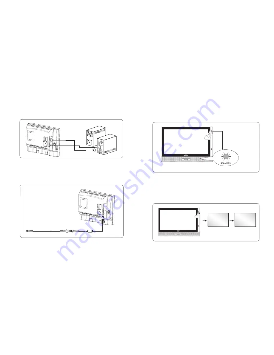
* VGA Input:
This unit provides VGA (Computer) input connector.
1. Connect computer VGA output to the monitor VGA input using VGA cable.
2. To connect audio source, using audio cable to connect from computer audio output to
VGA audio input.
Computrer Box
5. Basic Functions :
1. When POWER indication LED on unit turns RED in color indicating power is connected.
2. Press the "Power" button on the remote control, the POWER indication LED on the TV
Front Panel will turn "GREEN in color".
* POWER SIGNAL:
Power Indication LED
* MODE:
1. Press the "Mode" button on the TV front panel or "SOURCE" button on remote control
to select from the various mode settings.
2. The mode setting status will change each time the "Mode" or "SOURCE" button is
pressed – "AV1/AV2/CH 00"
** Please make sure video source is been connected properly.
AV2
AV1
CHANNEL
Noted: When connect VGA input, please set OSD (AV1 Select) to "PC" to view VGA
source.
Connect Power:
Connect to the power source using the power cable and adapter provided.
ATTENTION:
Ensure the power supply is connected to the unit. When not using unit for
a long period of time, remove DC input socket from the main power point.
DC INPUT
SOCKET
DC 12V


