Jensen Heavy Duty JHD3620 Installation And Operation Manual Download Page 5

JHD3620

3

INSTALLATION

This unit is designed for installation in vehicle cabs with an existing 1-DIN radio opening. In 
many cases, a special installation kit will be required to mount the radio to the dashboard. See 
the dealer where the radio was purchased for kit availability. Always check the kit application 
before purchasing to make sure the kit works with your vehicle.

Before You Begin

1.

Disconnect Battery

Before you begin, always disconnect the battery negative terminal.

2.

Remove Transport Screws

Important Notes

Before final installation, test the wiring connections to make sure the unit is connected 
properly and the system works.

Use only the parts included with the unit to ensure proper installation. The use of 
unauthorized parts can cause malfunctions.

Consult with your nearest dealer if installation requires the drilling of holes or other 
modifications to your vehicle.

Install the unit where it does not interfere with driving and cannot injure passengers during 
a sudden or emergency stop.

If the installation angle exceeds 30º from horizontal, the unit might not give optimum 
performance.

Avoid installing the unit where it will be subject to high temperatures from direct sunlight, 
hot air, or from a heater, or subject to excessive dust, dirt or vibration.
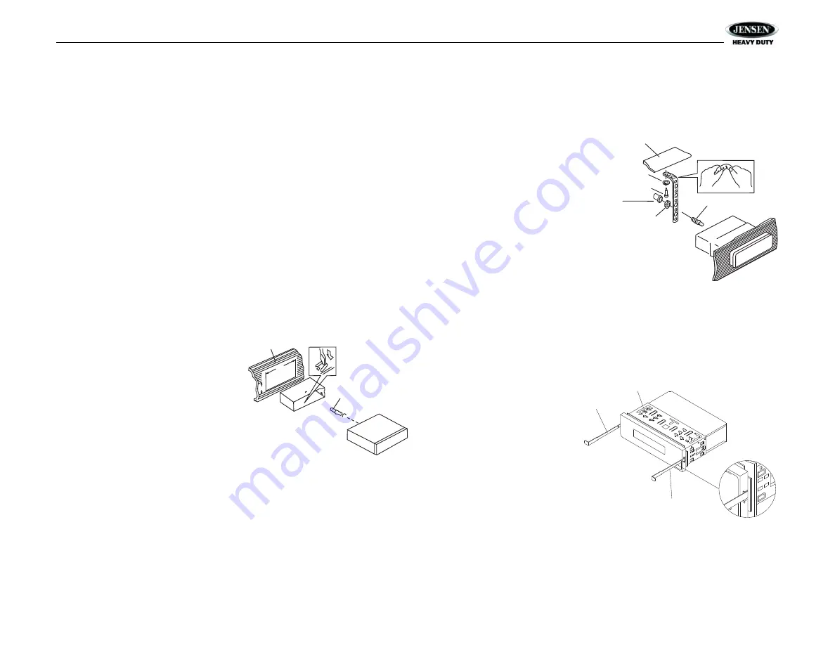
DIN Front Mount

1.

Slide the mounting sleeve off of the chas-
sis if it has not already been removed. If it 
is locked into position, use the removal 
keys (supplied) to disengage it. The 
removal keys are depicted in “Removing 
the Unit” on page 3.

2.

Check the dashboard opening size by 
sliding the mounting sleeve into it. If the 
opening is not large enough, carefully cut 
or file as necessary until the sleeve easily 
slides into the opening. Do not force the 
sleeve into the opening or cause it to bend 
or bow. Check that there will be sufficient 
space behind the dashboard for the radio chassis.

3.

Locate the series of bend tabs along the top, bottom and sides of the mounting sleeve. 
With the sleeve fully inserted into the dashboard opening, bend as many of the tabs 
outward as necessary to firmly secure the sleeve to the dashboard.

4.

Place the radio in front of the dashboard opening so the wiring can be brought through the 
mounting sleeve.

5.

Follow the wiring diagram carefully and make certain all connections are secure and 
insulated with crimp connectors or electrical tape to ensure proper operation. 

6.

After completing the wiring connections, turn the unit on to confirm operation (vehicle 
accessory switch must be on). If the unit does not operate, recheck all wiring until the 

problem is corrected. Once proper operation is achieved, turn the accessory switch off 
and proceed with final mounting of the chassis.

7.

Carefully slide the radio into the mounting sleeve making sure it is right-side-up until it is 
fully seated and the spring clips lock it into place.

8.

Attach one end of the 
perforated support strap 
(supplied) to the screw 
stud on the rear of the 
chassis using the hex nut 
provided. Fasten the 
other end of the 
perforated strap to a 
secure part of the 
dashboard either above 
or below the radio using 
the screw and plain 
washer provided. Bend 
the strap, as necessary, 
to position it. Some 
vehicle installations 
provide cavity for rear 
support. In these applications, place the rubber bushing over the screw stud and insert 
the radio.

CAUTION: The perforated rear support strap or rear rubber mounting bushing must 
be used in the installation of the radio. Installation without either may result in 
damage to the radio or the mounting surface and void the manufacturer’s warranty

.

9.

Test radio operation by referring to the operating instructions for the unit.

Removing the Unit

To remove the radio after 
installation, remove the plastic end 
caps, insert the removal keys 
straight back until they click, and 
then pull the radio out. If removal 
keys are inserted at an angle, they 
will not lock properly to release the 
unit.

Reconnect Battery

When wiring is complete, reconnect 
the battery negative terminal.

182

53

Dashboard

Bend Tabs

Screw Stud

Dashboard

Plain Washer

Screw (5 x 25mm)

Hex Nut (5mm)

Screw Stud

Support Strap

Rubber Bushing

Removal Key

Sleeve

Removal Key

Summary of Contents for Heavy Duty JHD3620

Page 1: ...ation Manual AM FM RBDS WB CD USB AUX IN iPod Ready SIRIUS Ready Heavy Duty Radio CAT CAT DN UP INFO ENTER INFO ENTER PTY CAT MENU PTY CAT MENU DISP SCROLL DISP SCROLL AS PS FAV AS PS FAV JHD3620 Guide d installation et d opération ...

Page 2: ...uction 1 Safety Information 2 Installation 3 Wiring 4 Basic Operation 5 Tuner Operation 8 CD MP3 USB Playback 10 Satellite Radio Operation 11 iPod Operation 13 Care and Maintenance 14 Troubleshooting 14 Specifications 15 CONTENU ...

Page 3: ...nology Mute Pre set Equalizer 5 settings Flat Rock Pop Classical User Electronic Bass Treble Balance and Fader Controls Output Power 45W x 4 Clock 12 24 Hour Selectable Public Announcement PA Feature with Optional Microphone sold separately IR Wireless Remote Control Ready sold separately 2 Channel Pre amp Line Level Outputs 2 Wire Power with Non Volatile Memory and Clock Time Support Auxiliary Au...

Page 4: ...ing on the recording status conditions of the disc and the equipment used for recording some CD Rs CD RWs may not play on this unit For more reliable playback please adhere to the following recommendations Use CD RWs with speed 1x to 4x and write with speed 1x to 2x Use CD Rs with speed 1x to 8x and write with speed 1x to 2x Do not play a CD RW which has been written more than 5 times Compatible D...

Page 5: ...ly inserted into the dashboard opening bend as many of the tabs outward as necessary to firmly secure the sleeve to the dashboard 4 Place the radio in front of the dashboard opening so the wiring can be brought through the mounting sleeve 5 Follow the wiring diagram carefully and make certain all connections are secure and insulated with crimp connectors or electrical tape to ensure proper operati...

Page 6: ...JHD3620 4 WIRING ...

Page 7: ...n buttons do not operate error symbol on the display Use a ball point pen or thin metal object to press the RESET button 23 This may be necessary should the unit display an error code Audio Menu Press the AUDIO button 3 to access the audio menu You can navigate through the audio menu items by pressing the AUDIO button repeatedly Once the desired menu item appears on the display adjust that option ...

Page 8: ... _ _ _ SAME Code 3 _ _ _ _ _ _ SAME Code 4 _ _ _ _ _ _ SAME Code 5 _ _ _ _ _ _ SAME Code 6 _ _ _ _ _ _ SAME Code 7 _ _ _ _ _ _ Battery Alarm Off On Battery Auto Off Off On Reset System Defaults ENTER Press the INFO ENTER button 16 to return the EEPROM to factory default set up values Update Firmware ENTER Press the INFO ENTER button 16 to apply recent software updates Equalizer Press the EQ LOUD b...

Page 9: ... view the clock set screen Press the INFO ENTER button to move to the next digit Press the TUNE SEEK 18 19 buttons to adjust the selected digit When no adjustment is made for five seconds the time will become set and normal operation will resume Scroll When the information is too long to be displayed on the LCD press the DISP SCROLL button 12 to view the entire title The information will scroll tw...

Page 10: ... band Press AS PS FAV 14 to scan stations stored in the current band The unit will pause for 5 seconds at each preset station Press AS PS FAV again to stop scanning when the desired station is reached RBDS Operation This unit is equipped to display RBDS Radio Broadcast Data Service information when broadcast by the radio station NOTE Radio stations broadcasting RBDS may not be available in your li...

Page 11: ...o the last known function mode See System Menu on page 6 to learn how to turn the WB Alert feature on SAME Decoding and Filtering Specific Area Message Encoding SAME data is also broadcast prior to alert broadcasts SAME data contains information about the geographic region affected by the alert the type of alert and its effective time The geographic region included in the SAME data is called the G...

Page 12: ...ss the 1 RPT button 8 during disc play to repeat the current track Press 1 RPT again to stop repeat play Random Play Press the 3 RDM button 5 during disc play to play all tracks in the current folder in random shuffled order Press 3 RDM again to stop random play Folder Navigation MP3 Only Press the PTY CAT MENU button 2 to view a list of all songs in the current folder Press the PTY CAT MENU butto...

Page 13: ...move to the third digit field 6 Press TUNE SEEK buttons to select the third digit 7 Press the INFO ENTER button to confirm the three digit channel and tune to the selected channel Storing Preset Channels The preset buttons 5 10 can be used to store 6 channels allowing convenient access to your favorite channels Programming Channels 1 Select the channel you want to store in memory 2 Press and hold ...

Page 14: ...mpted to enter your four digit code a Press the TUNE SEEK 18 19 buttons to enter the first digit b Press the INFO ENTER button to move to the next digit c Repeat above steps to enter all 4 digits 4 After entering the code you can navigate the list using the TUNE SEEK buttons to highlight the channels 5 Press the INFO ENTER button 16 to Lock indicated by a icon or Unlock the selected channel Favori...

Page 15: ...g RPT will appear on the LCD Press 1 RPT again to stop repeat playback Intro Play During playback press the 2 INT button 6 to play the first ten seconds of each song INT will appear on the LCD Press 2 INT again to stop intro playback Random Play During playback press the 3 RDM button 5 to play all songs in the current category in random order Random play will begin once the current song has finish...

Page 16: ...ption in a stationary environment home It is very important to understand the difference AM reception will deteriorate when passing under a bridge or when passing under high voltage lines Although AM is subject to environmental noise it has the ability to received at great distance This is because broadcasting signals follow the curvature of the earth and are reflected back by the upper atmosphere...

Page 17: ... 30dB 2 2μV Image Rejection 45 dB Stereo Separation 25 dB AM MW Frequency Range USA 530 1710 kHz Frequency Range Europe 522 1620 kHz Sensitivity S N 20dB 36 dB General Operating Voltage DC 12 Volts Grounding System Negative Ground Speaker Impedance 4 8 ohms per channel Tone Controls Bass at 100 Hz 10 dB Treble at 10 kHz 10dB Power Output 45W x 4 Idle Standby Current 75mA Current Drain 15 Ampere ma...

Page 18: ...ASA Electronics Corporation www asaelectronics com www jensenheavyduty com 2010 ASA Electronics Corporation v 120709 ...

Page 19: ...E strongest broadcast stations in your area BAND Press to select preset group FM1 FM2 FM3 AM1 or AM2 each with 6 channel memory locations WB Press hold to listen to WEATHERBAND VOLUME Rotate CLOCK W SE to NCREASE volume Rotate COUNTER CLOCKW SE to DECREASE volume MUTE Press to MUTE audio PTY CAT MENU Press to enter program type search Press or to navigate through program types Press PTY to select ...

Page 20: ...MUTE PLAY PAUSE Press to PLAY or PAUSE current audio NTRO SCAN Press when iPod is playing to play each track for 10 seconds in se quential order Press again to SELECT current song RDM Press when iPod is playing to play each track in RANDOM order Press again for NORMAL play D SP SCROLL Press to change display info between single and dual line text display Press hold to SCROLL Artist Song Title info...

Reviews: