Jennic
USB Programming Dongle
Reference Manual
2 Hardware Overview
2.1 Board Layout
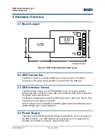
J6: USB
Connector
12
5
15
24
Dimensions in mm
U3: USB
Interface
Device
LED D2
RX
LED D1
TX
pin 1
J8
26
J1
pin 1
Figure 2: USB Programming Dongle Layout
2.2 USB Connection
The USB connector is a standard USB Type A male connector. This allows
connection to the power and serial data connections from the USB host.
2.3 USB Interface Device
The USB interface device is an FTDI FD232RL device. It is used to interface
between the data connections of the USB port and the standard UART connections
for UART0 of the JN5148 device.
For details of installing the royalty-free FTDI device driver, refer to the
JN51xx Flash
Programmer User Guide (JN-UG-3007)
.
Once the device driver is installed, the USB Programming Dongle will appear as an
additional COM port on the Windows PC.
2.4 Power Supply
The power for the USB Programming Dongle is sourced from the 5V connection on
the USB connector. The USB interface device generates a 3.3V supply which is
available on the Primary connector, J8 (see Section 2.6).
JN-RM-2056 v1.0
© Jennic 2010
7


