


12
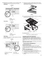
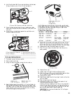
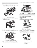
NOTE: If the template is misplaced, the following
measurements can be used to determine the vent hole
location.
4. Draw and cut a 6¼" (15.8 cm) diameter hole.
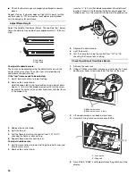
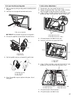
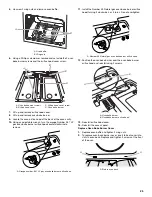
5. Remove the 4 locknuts on the blower side of the motor and
remove the bracket.
6. Lift and rotate the motor 90° to reposition the electrical
connection.
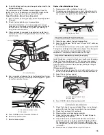
7. Rotate bracket 90° and secure with 4 locknuts.
8. Remove the bracket from the other side of the blower motor,
rotate 90° and secure with 4 locknuts.
Top View
A. 9" (22.8 cm)
B. 3
¹⁄₈
" (7.9 cm)
C. 8
³⁄₈
" (21.3 cm)
D. 6
³⁄₈
" (16.2 cm)
E. 2¼" (5.7 cm)
F. 12½" (31.7 cm)
G. 18¾" (47.6 cm)
H. 1½" (3.8 cm)
I. 3½" (8.9 cm)
A. Option 1
B. Option 2
View from Motor Side of Blower
A. Electrical connector
A
B
C
D
E
F
G
H
I
A
B
A
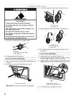
A. Electrical connector
A
Summary of Contents for W10526082A
Page 28: ...28 Notes ...