Jenn-Air W10394706A User Manual Download Page 9

9

Complete Connection

1. Open the manual shutoff valve in the gas supply line. The 

valve is open when the handle is parallel to the gas pipe.

2. Test all connections by brushing on an approved 

noncorrosive leak-detection solution. If bubbles appear, a 
leak is indicated. Correct any leak found.

3. Remove cooktop burner caps, burner bases and grates from 

parts package. Place burner bases on cooktop. Place burner 
caps on burner bases. Place grates over burners and caps.

4. Plug into a grounded 3 prong outlet.

5. Check the operation of the surface burners. See “Check 

Operation of Cooktop Burners” section in the “Complete 
Installation” section.

6. If your model has a griddle, see the “Install Griddle” section.

Install Griddle

(on griddle models)

The griddle is factory installed.

1. Place drip tray in the well at the front of the griddle. Slide tray 

toward the back until it stops.

2. Clean griddle before using. Refer to the Use and Care Guide.

Complete Installation

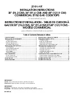
Install Burner Bases and Burner Caps

Install the burner base, making sure the igniter electrode is 
properly aligned with the base. Place burner caps on top of 
burner bases. If burner caps are not properly positioned, surface 
burners will not light.

Electronic Ignition System

Initial lighting and gas flame adjustments

Cooktop burners use electronic igniters in place of standing 
pilots. When the cooktop control knob is turned to any position, 
the system creates a spark to light the burner. This sparking 
continues, until the flame is lit or the knob is turned to Off.

Check Operation of Cooktop Burners

Push in and turn each control knob to the “LITE” position.

The surface burners and grill flames should light within 
4 seconds. The first time a burner is lit it may take longer than 
4 seconds to light because of air in the gas line.

After verifying the proper burner operation, turn the control knobs 
to OFF. 

If burners do not light properly:

Turn cooktop control knob to the “OFF” position. 

Check that the cooktop is plugged in and the circuit breaker 
has not tripped or the fuse has not blown. 

Check that the gas shutoff valves are set to the “open” position. 

Check that burner caps are properly positioned on burner 
bases.

Repeat start-up. If a burner does not light at this point, contact 
your dealer or authorized service company for assistance.

If you need Assistance or Service:

Please reference the “Assistance or Service” section of the Use 
and Care Guide or contact the dealer from whom you purchased 
your cooktop.

A. Closed valve
B. Open valve

A. Griddle drip tray
B. Griddle

A

Electrical Shock Hazard

Plug into a grounded 3 prong outlet.

Do not remove ground prong.

Do not use an adapter.

Do not use an extension cord.

Failure to follow these instructions can result in death, 
fire, or electrical shock.

WARNING

A

B

20,000 Btu/h Ultra Power™ Dual-Flame Burner

A. Incorrect
B. Correct

15,000 Btu/h Professional Burner

A. Incorrect
B. Correct

5,000 Btu/h Simmer/Melt Burner

A. Incorrect
B. Correct

A

B

A

B

A

B

Summary of Contents for W10394706A

Page 1: ...14 WIRING DIAGRAMS 15 S CURIT DE LA TABLE DE CUISSON 17 EXIGENCES D INSTALLATION 18 Outillage et pi ces 18 Exigences d emplacement 18 Sp cifications lectriques 21 Sp cifications de l alimentation en g...

Page 2: ...eath Do not store or use gasoline or other flammable vapors and liquids in the vicinity of this or any other appliance WHAT TO DO IF YOU SMELL GAS Do not try to light any appliance Do not touch any el...

Page 3: ...plate The model serial rating plate is located on the underside of the cooktop burner base It is recommended that a 600 CFM or larger vent hood be installed above the cooktop It is not recommended th...

Page 4: ...cm C 7 18 8 cm D Gas inlet is located 1 4 8 cm from the back of the cooktop burner base and 4 12 4 cm in from left hand side of the cooktop burner base E 22 55 9 cm F 3 8 4 cm G 1 4 cm A Grounded 3 p...

Page 5: ...tout to gas opening cutout H 6 16 1 cm gas opening cutout depth I 12 31 7 cm gas opening cutout width J 22 56 5 cm cabinet cutout depth K 2 5 1 cm cabinet side to gas cutout L 6 15 2 cm min distance o...

Page 6: ...al for use with Natural gas or after proper conversion for use with LP gas This cooktop is factory set for use with Natural gas To convert to LP gas see the Gas Conversion instructions provided in the...

Page 7: ...y Pressure Testing Gas supply pressure for testing regulator must be at least 1 water column pressure above the manifold pressure shown on the model serial rating plate Line pressure testing above psi...

Page 8: ...required depending on your installation 4 Place cooktop into the countertop cutout NOTE Check that the front edge of the cooktop is parallel to the front edge of the countertop If repositioning is nee...

Page 9: ...to any position the system creates a spark to light the burner This sparking continues until the flame is lit or the knob is turned to Off Check Operation of Cooktop Burners Push in and turn each cont...

Page 10: ...ght the burner using a butane extension lighter 11 Remove the control knob 12 Use a x 4 flat blade screwdriver to adjust the flame height Tighten screw to reduce flame height Loosen screw to increase...

Page 11: ...nch turning the access cap counterclockwise 2 Remove spring retainer from the cap by pushing against the flat side of the spring retainer Look at the spring retainer to locate the NAT or LP position T...

Page 12: ...ut Set gas orifice spud aside 5 Replace with correct LP gas orifice spud See the LP Gas Orifice Spud Hood Chart Use the following chart to find the exact orifice spud placement Fully insert choke into...

Page 13: ...system by closing its individual manual shutoff valve during any pressure testing of the gas supply piping system at test pressures equal to or less than psi 3 5 kPa To Convert Surface Burners 1 If in...

Page 14: ...r proper cooktop burner flame is very important The small inner cone should have a very distinct blue flame 0 64 cm to 1 3 cm long The outer cone is not as distinct as the inner cone LP gas flames hav...

Page 15: ...o Cooktop Stand Alone Version GND G Power Cord Griddle Spare Grill Spare Main Harness Power Spare R W BK W R Reignition Module Cooktop Front View GND BK W BK W W BK BK R N L Control Input Electrodes O...

Page 16: ...3 SW4 L N Y OR BU R 2 1 4 3 Power Cord Only To Cooktop Stand Alone Version Main Harness Power Spare Griddle Spare Grill Spare Cooktop Front View LEGEND Ground Chassis Plug With Female Connector Recept...

Page 17: ...ence ou d autres vapeurs ou liquides inflammables proximit de cet appareil ou de tout autre appareil lectrom nager QUE FAIRE DANS LE CAS D UNE ODEUR DE GAZ Ne pas tenter d allumer un appareil Ne pas t...

Page 18: ...tique des num ros de mod le et de s rie est situ e sur la face inf rieure de la base de br leur de la table de cuisson Il est recommand qu une hotte de cuisini re de 600 CFM ou plus soit install e au...

Page 19: ...rouve 1 4 8 cm de l arri re de la base du br leur de la table de cuisson et 4 12 4 cm du c t gauche de la base du br leur de la table de cuisson E 22 55 9 cm F 3 8 4 cm G 1 4 cm A La prise de courant...

Page 20: ...z H 6 16 1 cm de profondeur de l ouverture d coup e pour la canalisation de gaz I 12 31 7 cm de largeur de l ouverture d coup e pour la canalisation de gaz J 22 56 5 cm de profondeur de l ouverture d...

Page 21: ...3 1 ou CAN CGA B149 IMPORTANT Les tests de fuite de la table de cuisson doivent tre effectu s selon les instructions du fabricant Type de gaz Gaz naturel La conception de cette table de cuisson a t ho...

Page 22: ...t tre comme suit pour un fonctionnement correct Gaz naturel Pression minimum 6 15 2 cm colonne d eau Pression maximum 14 35 5 cm colonne d eau Gaz propane Pression minimum 11 27 9 cm colonne d eau Pre...

Page 23: ...22 9 cm Raccordementaugaz Assemblage du d tendeur 1 Placer la table de cuisson en appui sur le c t ou la face arri re avec l aide de deux personnes ou plus 2 Connecter le raccord flexible d acier ino...

Page 24: ...ordement 1 Ouvrir le robinet d arr t manuel sur la canalisation de gaz Le robinet est ouvert lorsque la manette est parall le la canalisation 2 V rifier tous les raccordements en les badigeonnant d un...

Page 25: ...F arr t V rifier que la table de cuisson est branch e que le disjoncteur ne s est pas d clench et qu aucun fusible n est grill V rifier que chaque robinet d arr t de gaz est la position open ouverture...

Page 26: ...cessitant un r glage 17 R installer la console de commande Soutenir la console de commande par le milieu avec un bras et reconnecter les connecteurs du commutateur de la plaque frire et ou le connect...

Page 27: ...ester le d tendeur sous une pression sup rieure d au moins 1 colonne d eau la pression de la tubulure de distribution indiqu e sur la plaque signal tique Pressurisation une pression sup rieure lb po 1...

Page 28: ...ccordement au gaz pour le raccordement correct de la table de cuisson la canalisation d alimentation en gaz 2 Pour l allumage et l utilisation corrects du br leur ainsi que le r glage des flammes sur...

Page 29: ...ation une pression de lb po 14 colonne d eau ou moins La table de cuisson devra tre isol e des canalisations d alimentation en gaz par la fermeture du robinet d arr t manuel individuel durant tout tes...

Page 30: ...ermique minimum LO pour chaque br leur de la table de cuisson Il est tr s important de v rifier l tablissement de flammes correctes sur les br leurs de la table de cuisson Le petit c ne interne doit c...

Page 31: ...BL R N BL N BL BL N N R NEU L Entr e de commande Sortie des lectrodest Module de rallumage R R R R R R MAR JA VE NEU L R OR JA VE BL BU BU Source secondaire pour la plaque frire Cordon d alimentation...

Page 32: ...mentation uniquement la version de la table de cuisson autonome L GENDE MASSE CH SSIS FICHE AVEC CONNECTEUR FEMELLE PRISE AVEC CONNECTEUR MALE LECTRODE TRANSFOR MATEUR CONTACTS DU RELAIS VANNE SOLEN O...

Reviews: