


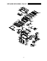
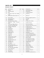


PARTS LIST
24
M
odel No. 730-0337
REF# DESCRIPTION
Q’TY
REF#
DESCRIPTION
QTY
01
Main Lid
1
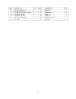
37
Front Trim Panel, Right
1
02
Temperature Gauge
1
38
Warming Rack
1
03
Logo
1
39
Cooking Grid With Hole
3
04
Temperature Gauge Heat Insulating
spacer
4 40
Flame
Tamer
4
05
Main Lid Handle Heat Insulating Cover
2
41
Main Burner
4
06
Main Lid Handle
1
42
Main Burner Igniter Wire (A.B.C.D)
1
07
Rotisserie Igniter Wire
1
43
Rear Baffle
1
08 Rotisserie
Burner
1
44 Lamps
2
09
Rotisserie Burner Gas Collector
1
45
Rotisserie Burner Flex Gas
1
10
Thermocouple Bracket (Rotisserie
Burner)
1
46
Rotisserie Gas Valve
1
11
Thermocouple (Rotisserie Burner)
1
47
Electronic Igniter Module
1
12
Rotisserie Orifice W/Brass Elbow
1
48
Side Burner Hose W/Quick Connector
1
13
Main Burner Bowl Assembly
1
49
NG Brass Connector
1
14
Front Baffle
1
50
NG Regulator Hose (6’’)
1
15
Main Gas Valve
4
51
NG Hose With Quick Connector (12’)
1
16
Main Manifold
1
52
Regulator, NG
1
17
Gas Valve Clamp
5
53
NG Regulator Bracket
1
18
Main Control Panel
1
54
Transformer
1
19
On/off Switch
1
55
Transformer Supporting Box
1
20
Control Knob
6
56
Transformer Box Waterproof Spacer
1
21
Grease Tray
1
57
Transformer Supporting Box Cover
1
22
Grease Tray Front Trim Piece
1
58
Cart Frame, Front
1
23
Side Shelf Push Bar, Left
1
59
lamps fix bracket
1
24
Side Shelf, Left
1
60
Door Hinge Bracket, Top (Left)
1
25
Side Shelf Front Panel, Left
1
61
Door Hinge Bracket, Top (Right)
1
26
Side Panel, Left
1
62
Power Supply Box Firmware
1
27
Bottom Panel, NG
1
63
Rubber Grommet
2
28
Door Magnet
4
64
Back Panel
1
29
Swivel Caster (3’’x 1 3/4’’)
2
65
Right Top Panel
1
30
Door Hinge Bracket, Bottom (Left)
1
66
Side Panel, Right
1
31
Condiment Rack
1
67
Sear Burner Igniter Wire
1
32
Door Hinge Bracket, Bottom (Right)
1
68
Side Burner Lid Hinge Rod
1
33
Front Trim Panel, Left
1
69
Side Burner Lid
1
34
Front Door, Left
1
70
Side Burner Cooking Grid
1
35
Door Handle
2
71
Sear Burner
1
36
Front Door, Right
1
72
Side Burner Bowl Assembly Frame
1


