background image


16 

SPARE PARTS LISTS 


240V 


Part 

Description 

Spare Part Number 

Comments 

PUMP 


05761003 

240V RED BODY 

PCB 

MAIN 

62020002 

240v MAIN CONTROL PCB - 
TESTED 

PCB 

REMOTE 

62020505 

TESTED w/o BUTTON TOPS OR 
KNOBS 

HEAT 
EXCHANGE 

COMPLETE 


COMPLETE BUILT UP HEAT 
EXCHANGE c/w BRASS FITTINGS 

HEAT 
EXCHANGE 

BARE Inc BRASSWORK 

26460670 

BARE EXCHANGE (No insulation 
or casework) c/w BRASS FITTINGS 

HEAT 
EXCHANGE 

BRASSWORK ONLY 

26460170 

BRASS FITTINGS ONLY 

HEAT 
EXCHANGE 

CASEWORK 

n/a 

CASEWORK AVAILABLE 
SEPARATELY - CONTACT jem-
[email protected] 

HEAT 
EXCHANGE 

INSULATION 

26520070 

PRE CUT INSULATION KIT 

HEAT 
EXCHANGE 

THERMAL TRIP ONLY 

05041021 

TRIP SWITCH ONLY 

HEAT 
EXCHANGE 

THERMAL TRIP Inc LOOM 


TRIP SWITCH INCLUDING LOOM 

CASEWORK 

CARRY HANDLE (PLASTIC) 

19200050 

PLASTIC CARRY HANDLE 

CASEWORK 

TOP LID 

26561670 

TOP LID 

CASEWORK 

MAIN CHASSIS 

26561660 

MAIN CHASSIS - BARE 

CASEWORK 


OTHER CASEWORK IS 
AVAILABLE - CONTACT jem-
[email protected] 

OTHER 

BOTTLE 

34300521 

2.5L FLUID BOTTLE 

OTHER 

REMOTE CONTROL 
ANALOGUE 

92765002 

COMPLETE ANALOGUE REMOTE 
CONTROL 

OTHER 

REMOTE CONTROL DMX 

92765015 

COMPLETE DMX INTERFACE / 
REMOTE CONTROL 

OTHER 

FLUID LINE ASSEMBLY 

62520045 

INCLUDES CAP, FILTER AND 
CONNECTOR 

OTHER 

MAINS SWITCH 

05523021 

ILLUMINATED MAINS ON/OFF 
SWITCH 

OTHER 

WIRING LOOMS COMPLETE 


ALL WIRING LOOMS FOR 
MACHINE 

OTHER 

STICKERS COMPLETE 


ALL STICKERS / LABELS FOR 
MACHINE 


Summary of Contents for ZR12-AL

Page 1: ......

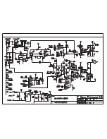
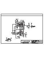
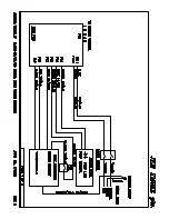
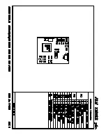
Page 2: ... I use with my machine 6 What can my machine do 6 Specifications 7 Service of machines Tools and optional extras 9 Machine Overview 10 Opening The Machine 11 Inside The Machine 11 How To How To Change A Heat Exchanger 12 How To Change A Pump 13 How To Change A PCB 14 Control PCB 14 Calibration 15 Spare Parts Lists Spare Parts 240V 16 Spare Parts 110V 17 Appendix Fuse Ratings 17 PCB Schematics 18 ...

Page 3: ...lement This is controlled by a J Type thermocouple fitted to the heat exchanger The temperature is determined by the calibration of the main control PCB Once the working temperature is reached the main control PCB will allow the pump to be operated and the machine will now be ready to run Haze machine principles The JEM ZR24 7 and Magnum Hazer work on the same smoke generation principles as the JE...

Page 4: ...ical appliances These standards reference the following European standards Emissions EN 55 022 B RF voltage and field strength EN 60 555 Harmonic current content EN 55 014 RF voltage discontinuous Immunity IEC 801 2 Electrostatic discharge to case IEC 801 4 Common mode fast transients These standards also meet the requirements of CISPR 22 JEM did not carry the CE mark on products that were produce...

Page 5: ...t hand side of the screen there are several different categories Click on SUPPORT This will bring you to the SMOKE USER SUPPORT page If you have a LOGIN NAME AND PASSWORD then press the LOGIN icon at the top of the page and enter your username and password into the relevant boxes If you do not have a LOGIN NAME you can still use the site just with limited access to information Select SMOKE from th...

Page 6: ...result of classical Jem design principles Electronic pump ramping provides continuous and even fog output Soft start electronics gives a low level of operating noise ideal for TV and theatre environments Overheat protection is provided by the Direct Thermal Protection device Output has been enhanced through a 1000W vaporizing chamber and unlike other machines of its size the ZR12 AL is extremely q...

Page 7: ... power US models 110 120 V nominal 60 Hz Main fuse 220 240 V power 5 AT slow blow Main fuse 110 120 V power 10 AT slow blow Typical Power and Current US model 110 V 60 Hz 1070 W 9 72 A 115 V 60 Hz 1169 W 10 16 A 120 V 60 Hz 1273 W 10 61 A EU model 220 V 50 Hz 899 W 4 08 A 230 V 50 Hz 982 W 4 27 A 240 V 50 Hz 1070 W 4 45 A Measurements made at nominal voltage Allow for a deviation of 10 Thermal Max...

Page 8: ...Main fuse 220 240 V power 5 AT slow blow Main fuse 110 120 V power 10 AT slow blow Typical Power and Current US model 110 V 60 Hz 1070 W 9 72 A 115 V 60 Hz 1169 W 10 16 A 120 V 60 Hz 1273 W 10 61 A EU model 220 V 50 Hz 899 W 4 08 A 230 V 50 Hz 982 W 4 27 A 240 V 50 Hz 1070 W 4 45 A Measurements made at nominal voltage Allow for a deviation of 10 Thermal Maximum ambient temperature Ta max 40 C Exte...

Page 9: ...size small and medium Wrenches 7mm 12mm x2 Pliers Needle Nose small Wire Cutters small Digital Multi Meter With ability to measure mV Additional Items recommended Cable Ties p n 13104000 Silicone Sealant JEM Calibration Box p n 92620005 Paper towels or other absorbent material Ammeter For measuring current draw of machine could be handheld or bench mounted Epsilon 5 Portable ISP Programmer p n 505...

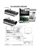
Page 10: ...10 ZR12 MACHINE OVERVIEW The Outside ANALOGUE CONTROL 3 PIN DMX ANALOGUE LINK STATUS LIGHTS ...

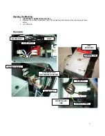
Page 11: ... 10 M4x10 pozidrive TAPTITE screws from the outside of the machine and store safely 3 Lift off the lid The Inside PUMP MAINS INPUT EARTH POINT THERMOCOUPLE ANALOGUE LINK NOT REMOTE SOCKET MAINS INPUT HEAT EXCHANGE THERMAL TRIP ELEMENTS BRASS FITTINGS COPPER FLUID LINE ...

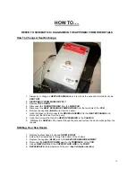
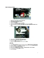
Page 12: ... connects the BRASS ASSEMBLY to the HEAT EXCHANGE and disconnect the fluid line from the pump 8 Undo the 4 screws that hold the HEAT EXCHANGER to the CHASSIS 9 Withdraw the NOZZLE of the heater through the hole and remove the heat exchange from the chassis Refitting Your New Heater 1 Replace heat exchange in chassis NOZZLE FIRST 2 Screw the 4 screws back in through the bottom of the chassis 3 Repl...

Page 13: ...hook the rear RUBBER MOUNT from the pump 9 Withdraw the pump from the front RUBBER MOUNT 10 Remove the PUMP from the machine 11 Remove the BRASS FITTING from the front of the PUMP REFITTING 12 Fit the BRASS FITTING to the front of the pump using a THREAD SEALANT COMPOUND 13 Fit the new PUMP to the CHASSIS by inserting the front end first into the RUBBER MOUNT 14 Hook the rear mount onto the back o...

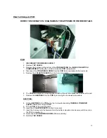
Page 14: ...TS from the 5 pin din sockets 6 The PCB is mounted on 2 mounting posts which will need to be squeezed to remove the pcb 7 Remove the HEATSINK from the PCB by removing the 2 screws nuts washers REFITTING 8 Fit the HEATSINK to the PCB using the 2 screws nuts adding THERMAL TRANSFER PASTE underneath component Q6 9 Fit new PCB to the mounting posts 10 Insert the 4 PLASTIC RIVETS into the din sockets 1...

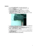
Page 15: ...EMPERATURE CALIBRATION POT until the RED HEATING LED FLASHES 8 IF YOU PRESS THE RAMP BUTTON IN THE LED SHOULD GO OUT AND COME BACK ON AGAIN WHEN YOU RELEASE THE BUTTON 9 Disconnect the CALIBRATION BOX from the THERMOCOUPLE connectors 10 Replace the THERMOCOUPLE onto the DMX PROGRAM PCB PRE 11 06 YELLOW BLUE POST 11 06 BLACK WHITE 11 Turn the machine on and check for current draw 12 Let the machine...

Page 16: ...ATION KIT HEAT EXCHANGE THERMAL TRIP ONLY 05041021 TRIP SWITCH ONLY HEAT EXCHANGE THERMAL TRIP Inc LOOM TRIP SWITCH INCLUDING LOOM CASEWORK CARRY HANDLE PLASTIC 19200050 PLASTIC CARRY HANDLE CASEWORK TOP LID 26561670 TOP LID CASEWORK MAIN CHASSIS 26561660 MAIN CHASSIS BARE CASEWORK OTHER CASEWORK IS AVAILABLE CONTACT jem service martin dk OTHER BOTTLE 34300521 2 5L FLUID BOTTLE OTHER REMOTE CONTRO...

Page 17: ...ONLY 05041021 TRIP SWITCH ONLY HEAT EXCHANGE THERMAL TRIP Inc LOOM TRIP SWITCH INCLUDING LOOM CASEWORK CARRY HANDLE PLASTIC 19200050 PLASTIC CARRY HANDLE CASEWORK TOP LID 26561670 TOP LID CASEWORK MAIN CHASSIS 26561660 MAIN CHASSIS BARE CASEWORK OTHER CASEWORK IS AVAILABLE CONTACT jem service martin dk OTHER BOTTLE 34300521 2 5L FLUID BOTTLE OTHER REMOTE CONTROL ANALOGUE 92765002 COMPLETE ANALOGUE...

Page 18: ......

Page 19: ......

Page 20: ......

Page 21: ......

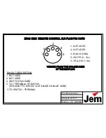
Page 22: ... THE DIN PLUG 5 TO TERMINAL OF SWITCH STRAIGHT TO SWITCH NOT DIODE ON BLUE WIRE PIN OUT DESCRIPTION 1 NOT USED 4 NOT USED 2 GND TO DMX CARD 3 TO SWITCH TERMINAL ZR12 DMX REMOTE CONTROL XLR PLUG PIN OUTS 1 NOT USED 4 NOT USED 5 WHITE 0 10v 3 YELLOW 16v 2 BLACK GND ZR12 DMX Remote Pins ...

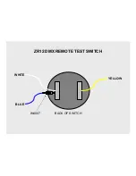
Page 23: ...YELLOW BLUE WHITE ZR12 DMX REMOTE TEST SWITCH BACK OF SWITCH IN4007 ...

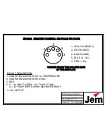
Page 24: ...10v INPUT NEEDS 1 5v TO HEAT AND 2v 10v PUMP SPEED WHEN MACHINES READY PIN OUT DESCRIPTION 1 GND WHEN MACHINES UP TO TEMPERATURE 4 GND WHEN MACHINES HEATING 2 GND 3 16v OUTPUT ZR12AL REMOTE CONTROL DIN PLUG PIN OUTS 1 YELLOW READY 4 WHITE HEAT 5 BLUE 0 10v 3 RED 16v 2 BLACK GND ZR12AL Remote Plug Pin ...

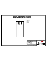
Page 25: ...Drawn by GS 28 03 2006 ZR12AL REMOTE PCB PIN OUTS Drawing No 2011 2A 1 2 3 PIN 1 BLACK 2 BLUE 3 RED ZR12AL REMOTE PCB PIN OUTS ...

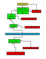
Page 26: ...fully heated and ready to run Check power and turn on See HEATER PROBLEMS Is the pump running See PUMP PROBLEMS Undo the brass fitting to the heater fluid line and run the machine Is fluid coming out of the brass fitting Pump seized Replace pump Heater is blocked Replace heater YES NO NO NO NO YES YES YES ...

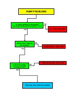
Page 27: ...ing to the pump set to full power and check 240V 110V See PCB PROBLEMS Does piston seem to be moving Is fluid travelling through pump PUMP SEIZED REPLACE PUMP BLOCKED REPLACE Fault may be in fluid line heater NO YES YES YES NO NO ...

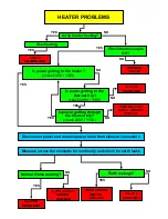
Page 28: ... loom from element connectors Is power getting to the heater check 240V 110V Measure across the elements for continuity and check for earth leaks Normal Ohms reading OPEN CIRCUIT HEATER REPLACE See PCB PROBLEMS Earth leakage See PCB PROBLEMS OPEN CIRCUIT HEATER REPLACE Is the heater heating Overheating CHECK CALIBRATION Check thermocouple OK REPLACE HEATER YES YES YES YES YES YES YES YES NO NO NO ...

Page 29: ...PCB PROBLEMS APART FROM THE OBVIOUS FUSES WIRING ETC PCB FAULT FINDING IS TOO IN DEPTH TO COVER HERE PLEASE REFER SERVICING REPAIR TO A QUALIFIED ENGINEER ...

Reviews: