background image

2

Introduction:

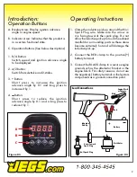
Operation Buttons

1.  R/A Button: 

Switch speed and ignition advance angle  

to be displayed.

2.  4/2 Button: 

Switch from 4-stroke and 2-stroke.

3.  + Button: 

Short press to increase the ignition 


advance angle by 0.1 and long press to  

increase it by 1.

4.     Button: 

Short press to reduce the ignition 


advance angle by 0.1 and a long press to  

reduce it by 1.

Figure 03

A

B

C

A. Display Area: Display ignition advance  

angle or engine speed.

B.  Indicator Area: Indicates that the product is 

in a certain functional state.

C.  Operation Buttons (See below descriptions)

1.  Clamp the inductive pick-up around the No.1 

Spark Plug wire. Make sure the arrow on 

it is facing towards the spark plug. Do not  

allow the inductive pick-up to touch the exhaust 

manifold or surrounding parts as these areas 

become extremely hot and will damage the 

inductive pick-up.

2.  Connect the RED clamp to the po)  

battery terminal.

3.  Connect the BLACK clamp to a secure engine 

ground such as the alternator bracket or the 

engine block. For safety reasons, do not use 

the negative(-) battery terminal or fuel system 

components as a ground connection point.

Black

Red

Battery

+

Distributor

No.1 Spark Plug

Lead Connections

Engine Block 

or Chassis

Induction 

Pick-Up

Arrow Toward 

Spark Plug

Figure 04

Operating Instuctions

Summary of Contents for 555-40750

Page 1: ...Digital Inductive Timing Light User Guide 555 40750 9 16 Volt ...

Page 2: ...op Dead Center When the timing is retarded the spark occurs after the piston has started to go down in the cylinder 1 T D C T D C T D C Pulley Timing Marks Pointer Before Top Dead Center B T D C Figure 01 T D C A D C Top Dead Center After Dead Center Introduction Contents 1 For checking and setting ignition timing on automotive agricultural and marine engines 2 For use on 9 16 volt systems 3 Rever...

Page 3: ...low descriptions 1 Clamp the inductive pick up around the No 1 Spark Plug wire Make sure the arrow on it is facing towards the spark plug Do not allow the inductive pick up to touch the exhaust manifold or surrounding parts as these areas become extremely hot and will damage the inductive pick up 2 Connect the RED clamp to the positive battery terminal 3 Connect the BLACK clamp to a secure engine ...

Page 4: ...rotated in either direction 3 Locate engine timing mark and use a rag to clean all grease and dirt from the mark and the pointer It may help to use chalk or white paint on the mark to make it more easily seen 4 Start and run the engine until normal operat ing temperature is reached Approximately 15 minutes and then stop engine 5 Start the engine and operate at normal idle speed aiming the timing l...

Page 5: ... and unauthorized persons away from the working area 9 Always store the timing light in a safe dry and child proof location when not in use 10 Always run the engine in well ventilated areas 11 Always remember that a flashing timing light freezes rotating components Do not be tempted to touch an apparently stationary component which is in fact rotating 12 Never use the timing light if it is damaged...

Reviews: