


USER MANUAL
JEFC270T10B-230
270L
BELT DRIVEN AIR COMPRESSOR
•
TANDEM 2x 3HP
•
10Bar
www.jeffersontools.com
10
SAFETY VALVE
IMPORTANT:
The safety valves supplied with this equipment are designed and constructed for use exclusively with compressed air, free from
impurity. The materials used in construction are suitable for operating the valve at the rated pressure and temperatures. The viton or NBR gasket
conserves the resistance characteristics, even in prolonged use. The valve caulking is designed to impede calibration, modification or tampering.
Any modification or recalibaration of the safety valve will nullify warranty and potentially make the equipment unsafe. Ensure that the valve
pressure is no greater than the operating pressure of the tank or of the system that it is installed with.
•
Check that the discharge flow rate of the valve is greater than the quantity of the air to discharge.
•
The safety valve must be positioned directly on the tank in a vertical position, in a dry, accessible place protected against the weather and far
away from liquids or condensation.
•
It must be positioned to allow sufficient space all around for correct air discharge, without causing damage to persons or the surrounding
area.
•
The valve rod must be free in its movement when discharging.
•
The connection between the valve and the part to be protected must be free from all kinds of choking and be as short as possible so as not
to reduce the discharge flow rate of the valve itself.
•
The connection passage area must be greater than the valve orifice area.
•
During installation screw on the valve with a torque spanner using the hexagonal part of the body.
•
Apply a maximum torque of
30Nm
, paying attention not to cause any deformation; using pincers, pliers, hammers or tools other than a
hexagonal spanner is forbidden and will void warranty.
•
Check that the inlet hole and the shutter are not blocked by glue, Teflon or similar materials that could bind the shutter or other functional
components.
•
If the valve is replaced the compressed air contained in the system must be discharged first.
•
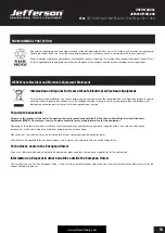
WARNING:
Jefferson Tools cannot take any responsibility for damage caused to persons and/or things due to failure to observe these
instructions.
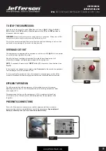
OPERATION GUIDE
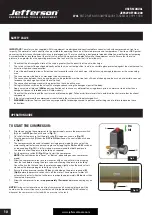
TO START THE COMPRESSOR:
•
Prior to connecting the compressor to the power supply, ensure the pressure switch
(
A)
is on the
OFF
position as shown in (
Fig. 9
).
•
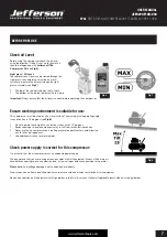
On initial start-up ensure that the drain valve (
C)
is open as shown in (
Fig.10)
.
•
Turn the power switch (
D)
from the
OFF
to
ON
position on the control box as shown
in (
Fig.11
).
•
The compressor can be used in tandem or single pump mode. You can select the
motor configuration for tandem and single use by toggling the
SA2
and
SA1
switches
as required (see
Fig.12
). On initial startup we recommened that both pumps are
turned on to allow the pressure to build up as required.
•
Pull the pressure switch
C
(
Fig.11
) up to start the compressor.
NOTE:
The switch may be a "Lever" or "Button", depending on your compressor
model.
•
Allow the compressor to run for a few minutes with air and any moisture escaping
from the tank before closing the drain valve and allowing the pressure to build up.
You will notice the the tone from the motor changing slightly when the drain valve is
closed as the pressure begins to build up in the tank.
•
Ensure the tank pressure reaches
10 bar
as indicated on the pressure gauge (
B)
(Fig.9)
before the pressure switch shuts off the motor. The compressor motor will
automatically restart when the tank pressure drops to approximately
3-4 bar
less than
the maximum pressure.
•
Allow the compressor to run for
approximately 10 minutes
before connecting any air
tools.
NOTE:
During correct operation a whistle of compressed air escaping/releasing will be
heard when the motor strops and a protracted whistle (
approximately. 20-30 seconds
)
whenever the compressor is started with no pressure in the tank.
A
B
On
Off
Fig.9
C
Fig.10


