background image

97/154

119635

Index G

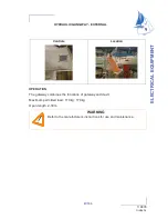
HYDRAULIC GANGWAY - EXTERNAL

OPERATION

The gateway combines the functions of gateway and davit.

Maximum permitted load: 110 kg: 170 kg

Open length: 2,30 m

Controls

Location

WARNING

Refer to the manufacturer's instructions for use and maintenance..

9

E

L

E

C

T

R

IC

A

L

 E

Q

U

IP

M

E

N

T

Summary of Contents for 53

Page 1: ...TERNAL OPERATION The gateway combines the functions of gateway and davit Maximum permitted load 110 kg 170 kg Open length 2 30 m Controls Location WARNING Refer to the manufacturer s instructions for...

Page 2: ...G BOW THRUSTER 24V Nozzle Layout of components Skipper s cabin 1 Battery set 4 x 50A 2 Fuse 315A 3 Isolation relay 4 Motor Relay coupler Batteries Changes the 12V circuit to 24V Breaker Location Port...

Page 3: ...in Inverter 1800W Breaker 16A Fuse 125A Control Location Unit Chart table Earth WARNING The cutting power 220V 110V dock or generator does not cut the power converter It is imperative to switch the co...

Page 4: ...the dock ADVICE RECOMMENDATION In order to reduce the risks of electic shock and fire Before you plug in or unplug the boat shore supply cable switch off the shut off device connected to the shore su...

Page 5: ...al installation Close the shore supply input cover firmly after use Do not modify the vessel shore supply line connections only use compatible connections Do not alter the vessel s electrical system T...

Page 6: ...e cabin hanging locker located in rear port A pictogram helps to locate it easily Logic controller piston and hydraulic pump either side of the rudder sector in the aft cabin To supply power to all el...

Page 7: ...103 154 119635 Index G ELECTRONIC LAYOUT OF COMPONENTS Log and depth sounder transducers View interior View Outside 9 ELECTRICAL EQUIPMENT...

Page 8: ...ILOT Access Port cockpit locker Gyrocompass Cubby hole locker Port aft cabin Vessel Management Unit Cubby hole locker Port aft cabin MAIN COMPONENTS 220V EXTRACTOR HOOD Socket 220V MICROWAVE Socket 22...

Page 9: ...ward cabin Ref 3 Compressor Aft cabin Cocon Ref 4 Socket Breaker 220V Ref 1 Seawater inlet Pump Ref 2 Maintenance of filters to engage in regular Close valves taken seawater Unscrew the top of the fil...

Page 10: ...106 154 119635 Index G Drainage Compressor Aft cabin Ref 5 Master switch Ref 7 Relay box Seawater pump Ref 6 Drainage Compressor Forward cabin Saloon Ref 8 Compressor Saloon Ref 9 Control...

Page 11: ...ater visually once the air conditioning starts running OPERATION Before starting the engine Open the raw water intake valves and evacuation valves Use the switch on the chart table to select the power...

Page 12: ...ex G GENERATOR SYNOPTIC REF Designation 1 Fuel filter 2 Sea water filter 3 Water trap 4 Anti siphon valve 5 Differential circuit breaker 6 Generator 7 Water Gas separator 8 Seawater inlet 9 Drainage S...

Page 13: ...109 154 119635 Index G GENERATOR Layout of components Generator Diesel filter Ref 1 Breaker Ref 2 Outlet Water trap Ref 3 9 ELECTRICAL EQUIPMENT...

Page 14: ...110 154 119635 Index G Water Gas separator Ref 4 Supply valve Generator Ref 5 Earth Ref 6 Seawater inlet Ref 7 Sea water filter Ref 8 WARNING Refer to the instructions for use...

Page 15: ...er generator switch located on the chart table OPERATION Supply Diesel The generator is fed by fuel through the fuel tank port The fuel filter reference 1 is located at the generator circuit Refrigera...

Page 16: ......

Page 17: ...113 154 119635 Index G ENGINE GENERAL INFORMATION ENGINE FITTING 10...

Page 18: ...114 154 119635 Index G Deck filler Diesel tank 237 litre Location Port aft cabin Gauge Location Electrical panel Refer to the instructions for use...

Page 19: ...ocate the extinguisher hole which allows access to the engine compartment if a fire should break out Refer to chapter 2 Filling Fill the fuel tank using the filler In order to protect the deck from po...

Page 20: ...116 154 119635 Index G ENGINE FITTING...

Page 21: ...valve 14 Expansion tank 15 Pre filter Fuel 16 Sleeve 17 Fan 18 Propeller 19 Bearing 20 Propeller shaft 35 mm diameter 21 Stern frame 22 Stern frame water intake 23 Stuffing box 35 mm diameter PRECAUTI...

Page 22: ...GINE REF Designation 1 Sea water filter 2 Anti siphon valve 3 Engine compartment ventilator 12V 4 Anti siphon valve 5 Diesel oil decanter valve 6 Stuffing box 7 Propeller shaft 8 Flange 9 Seawater inl...

Page 23: ...tion If water does not flow out Stop the engine immediately Check that the valve is open Close the water inlet valve if the boat is unattended for long Inspect and clean the water filter regularly Eng...

Page 24: ...120 154 119635 Index G SUPPLY VALVE FUEL ENGINE WATER INTAKE VALVE Fuel oil valve for engine Engine water intake valve...

Page 25: ...the engine s manual The second filter is on the pipe that links the tank to the engine it plays the role of a water decanter and prefilter Drain by undoing the knurled screw at the base of the decanta...

Page 26: ...n counter Tachometer 2 Control indicator lights 3 Step Stop 4 Pre heating Engine ignition kill drawing 1 Anode 2 Propeller 3 P bracket 4 Propeller shaft 5 Stuffing box 6 Connecting device Propeller de...

Page 27: ...y bank at the start of a new season for example risks damaging the onboard electrical system The forward and reverse travel of the boat are controlled by the engine control lever In passing from forwa...

Page 28: ...tronics at the electrical panel 3 If necessary according to auto pilot model put into STAND BY mode at the exterior helm station 4 Start the engine 5 Activate the bow thruster manually Steady green li...

Page 29: ...utch Mechanical linkage between the engine and the propeller shaft 5 TCU Transmission and Clutch Management interface between the clutch activator and the VMU 6 VMU Vessel Management Unit the brains o...

Page 30: ...6 154 119635 Index G LAYOUT OF COMPONENTS Rotating motor Ref 2 Clutch actuator Ref 3 TCU housing Transmission and Clutch Management Ref 5 VMU housing Vessel Management Unit Ref 6 Throttle actuator Ref...

Page 31: ...safety connector X6 normal X2 X2 B A X5 X3 Main Harness VMU T C U Harness V M U Termination resistor Filter box RPM sensor Angular steering sensor RPM sensor adapter Throttle acuator Joystick Side Mo...

Page 32: ...bow thruster control simultaneously To avoid this inconvenience and to protect the bow thruster we advise you not to use the bow thruster for more than 30 seconds at a time and to allow it to cool bet...

Page 33: ...control push button A steady light illuminates on the bow thruster control panel The system is operating Press the joystick button and hold down for 2 seconds before activating the joystick When the...

Page 34: ...lashing The joystick is operational the control lever is out of action The wheel turns to lock the helm and rudder along the longitudinal axis of the boat Be careful to keep arms clear of wheel as it...

Page 35: ...nal to the position of the joystick Push the joystick to port The boat moves to port Acceleration can be altered by turning the joystick clockwise boat accelerates anti clockwise boat decelerates and...

Page 36: ...starboard but the stern swings more quickly than the bow You can do the same to port Push the joystick to port Turn the joystick anti clockwise The boat moves to port but the bow swings more quickly...

Page 37: ...turn clockwise The boat moves forward and turns to starboard The acceleration is proportional to the position of the joystick Do the same manoeuvre turning anti clockwise The boat moves forwards and t...

Page 38: ...ntrol lever and bow thruster manually If control lever is not working apply emergency procedure SAFETY set out in owner s manual ZF Press the button for 1 second RAYMARINE version The auto pilot comes...

Page 39: ...ilst moving the throttle to the first forward notch then release the button WARM UP is only possible in forward gear To come out of WARM UP mode return the lever to neutral 6 Procedure for shutting do...

Page 40: ...to position the engine base of the boat correctly under the crane before stopping the boat s engine see the chapter Handling Every 7 years replace the POD s packing Check engine oil level The level mu...

Page 41: ...4 VMU power supply TCU 1 5 VMU power supply TCU 2 6 Supply VMU after engine contact 7 Supply TCU after engine contact 8 Supply pod after engine contact Motor supply 40A NOTE If a safety fuse illumina...

Page 42: ...138 154 119635 Index G DIAGRAM LOCATION...

Page 43: ...switch set 5 Diesel filter 6 Sea water filter 7 Anti siphon valve 8 Water heater 9 Engine control 10 Water trap 11 Exhaust outlet 12 Expansion tank 13 Engine panel 14 Ventilation Bilge 15 Filler cap...

Page 44: ......

Page 45: ...msman s field of visibility ADVICE RECOMMENDATION When the engine is running avoid making noise and chops near the other users Respect speed limits If this boat is equipped with a fixed blade propelle...

Page 46: ...154 119635 Index G EQUIPMENT Heating Diesel Layout of components Heater Ref 1 Diesel pump Ref 2 Supply Heating Ref 3 Control Ref 4 WARNING Refer to the manufacturer s instructions for use and maintena...

Page 47: ...is the result of tests carried out jointly with the engine manufacturer ADVICE RECOMMENDATION Check the whole propeller shaft several times a year Change the anode if necessary Check and change the c...

Page 48: ......

Page 49: ...145 154 119635 Index G LAUNCHING LAUNCHING RECOMMENDATIONS STEPPING THE MAST 11...

Page 50: ...146 154 119635 Index G POSITION OF HOISTING CRADLE AND STRAPS A Position of labels Note Measurements are expressed in mm 7 400 1000...

Page 51: ...oling water drain valves Retract the speedometer into its housing it may be damaged by the handling belts For the on line engines check the anode at the end of the shaft is in place Check the nut tigh...

Page 52: ...for tightness if need be Open the valves and make sure that they are tight with the hull and relevant hose Check the stuffing box for watertightness Refer to chapter 11 Stuffing box Before starting t...

Page 53: ...149 154 119635 Index G WINTER STORAGE LAYING UP PROTECTION AND MAINTENANCE 12...

Page 54: ...them back into the boat in the upright and side position in order to have minimum contact surfaces During long absence leave the fridge and icebox doors open to avoid mould developing EXTERIOR Thorou...

Page 55: ...switches grease the terminals and check the battery voltage Fill the fuel tanks to a maximum in order to avoid condensation Please refe to the engine manual for anything relating to the engine Ashore...

Page 56: ......

Page 57: ...BI BP 529 85505 LES HERBIERS cedex FRANCE Tel 33 02 51 64 20 20 Fax 33 02 51 67 37 65 Internet http www jeanneau com fr The present document is not contractual and since we constantly desire to improv...

Page 58: ......

Reviews: