Operation and Control Instructions 27
Placing individual nodes at the end of long branches or spokes from the middle of the bus should be
avoided. If branches are used, make them short. The preferred bus architecture is shown in Figure 5.
Figure 5: Preferred RS485 Bus Architecture
RS485 buses usually require line termination when fast transmissions, high data rates, or long
cables lengths are employed. Although no termination is required if the bus cable length is short and
transmission speed is low, it is always recommended.
Terminate bus lines at both ends of the main cable to prevent signal reflection. For example, in
Figure 5, termination is applied at the Master node and SKB n node.
The common method of termination is parallel line termination, whereby a resistor is placed across
the differential lines at the most extreme end of the bus (SKB n+1). The resistor value must be equal
to the characteristic impedance of the cable. In practice, the resistor value needs to be slightly higher
than characteristic impedance. A common mistake is to connect a terminating resistor at each node
in the RS485 bus. This action causes line problems when more than four nodes are connected
because the active bus driver is loaded excessively.
The maximum cable length specified for RS485 buses is 1219 meters (4000 feet). Generally, the
longer the cable length, the slower the data transmission rate. All applicable data baud rates used by
the SKB switch operate over the maximum cable length when proper termination is used and the
number of nodes does not exceed 31.
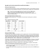
Addressing using the RS485 Serial Interface
The addresses are outlined in Table 7.
Each SKB switch is pre-assigned an address of 1. If an SKB device is reset (either hard or soft), and
the network address is 1, the ATTN line is asserted. The ATTN line is de-asserted when the device
address is changed to something other than 1. This feature acts as a mechanism for informing the
bus master that a device with the default address is connected to the bus. See the Application Note
section for details regarding implementation of the Attention (ATTN) line.
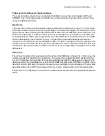
Protocol for the RS485 Serial Interface
A proprietary link-layer RS485 protocol has been developed that enables network-based communi-
cation utilizing a single master and multiple slaves on a common bus. The protocol provides a high-
level flow control mechanism (using acknowledge packets) and link-layer error detection (using CRC
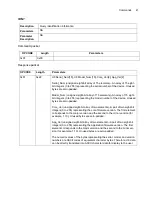
Table 7: RS485 Addresses
Address
Description
0
Reserved for master. Cannot be an SKB switch.
2 to 31
Valid address range for SKB devices.
255
Broadcast address. Packets sent with a broadcast address are received and
parsed by all active SKB devices on the RS485 bus.
Summary of Contents for SKB Series
Page 1: ...SKB SERIES FIBEROPTIC SWITCH MODULE User Manual ...
Page 2: ...ii 10109002 Rev 001 August 2001 2001 JDS Uniphase All rights reserved ...
Page 4: ...iv ...
Page 11: ...7 Contents ...
Page 13: ...9 List of Figures ...
Page 15: ...11 List of Tables ...
Page 19: ...4 Safety Information Instructions and Symbols ...
Page 25: ...10 Introduction ...
Page 53: ...38 Operation and Control Instructions ...
Page 91: ...76 Commands ...
Page 111: ...96 Application Notes ...
Page 113: ...98 Service ...


