2004 JCM – American, Corp.
Office:
(800) 683-7248
Technical Support:
(702) 651-3444
FAX:
(702) 651-0214
E-Mail:
[email protected]
Web-Site:
www.jcm-american.com
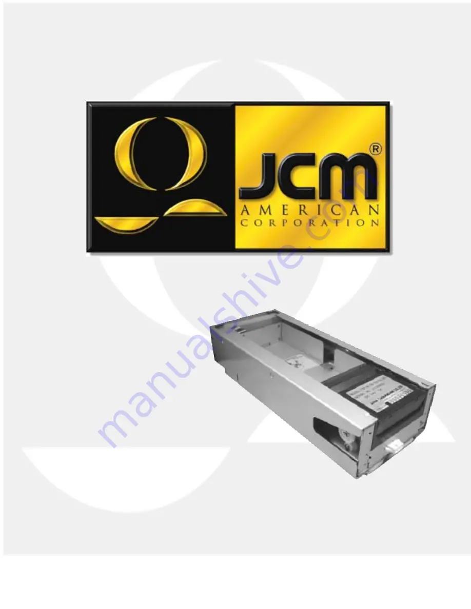
TSP - 02 Printer
Operation and Maintenance Manual (Rev. B)
JCM Part No. 960-000051
Page 1: ...n Corp Office 800 683 7248 Technical Support 702 651 3444 FAX 702 651 0214 E Mail techsupport jcm american com Web Site www jcm american com TSP 02 Printer Operation and Maintenance Manual Rev B JCM P...
Page 2: ......
Page 3: ...ts Introduction 1 Model Classification 2 General Specifications 3 Installation 5 Loading Paper 6 Pin Assignments 7 Dip Switch Settings 8 Maintenance 10 Sensor Adjustment 10 Cleaning 10 Exploded View 1...
Page 4: ......
Page 5: ...quality printing ability JCM provides the thermal paper specifications for optimum performance while allowing the customer the freedom to create a unique 4 color design on the top surface The thermal...
Page 6: ...put 04 No mounting brackets ribbon cable output 05 C type 288mm ribbon cable output 4 Paper capacity 2 200 notes Standard 3 300 notes 6 600 notes with extended hopper 5 Paper size 2 Fanfold paper 65 m...
Page 7: ...3A 50 print ratio Paper Hopper Capacity 200 standard With optional hopper extension 400 and 600 ticket capacity Recommended Thermal Paper Brand Kanzaki Part No TO 381N NOTE Using paper not recommended...
Page 8: ...sor Exit Sensor Paper Near End Sensor Paper Upper Tray Open Sensor Printer Removed Sensor Printing Method Dot Density Effective Print Dot Area Thermal line dot method 8 dots mm 480 dots wide 1200 dots...
Page 9: ...Installation 5...
Page 10: ...sure the Index mark is positioned properly Remove the band from the packet and drop it in the printer hopper Turn the printer ON Place the top sheet of paper in the entry opening as shown in photo Th...
Page 11: ...ta printer Photo coupler Isolation 5 IGND Isolated Ground 6 DC 24 V Printer Power Supply 7 GND Ground 8 DC 24 V Printer Power Supply 9 RCTR24 Modulated 24 V signal For showing status via LED 10 GND Gr...
Page 12: ...ustment data 0 0 1 1 Test pattern and version information 0 1 1 1 Motor function test 1 1 1 1 Sensor calibration DIP Switches 1 ON Up 0 OFF Down Normal Operating Setting Printer is interfaced with a h...
Page 13: ...d to test print quality This same test can be performed by pushing the white button next to the DIP switches Motor Function Test Test forward and reverse operation of the motor The green LED 1 is loca...
Page 14: ...and prints the appropriate data which may include bar code information A sensor in the hopper section indicates to the host when the paper supply is low There is also a sensor in the head that inform...
Page 15: ...Exploded View 11...
Page 16: ...ping Motor 1 19 071903 Idle Gear A 1 20 071905 Idle Gear B 1 21 079578 LED Harness 1 22 079532 Harness Protection Seat A 1 23 079525 Platen 1 24 079529 Upper Guide 1 25 079514 Platen Gear 1 26 034397...
Page 17: ...Black 2 49 M3 x 6 Bind P tight Black 5 50 3 E type Clip 8 51 M2 6 x 4 W SEMS Small 3 52 M3 x 5 Pan Screw Small 9 53 M2 x 8 Pan Screw P tight 2 54 2 x 8 Spring Pin 1 55 4 E type Clip 2 56 2 E type Clip...
Page 18: ...925 Pilot Road Las Vegas Nevada 89119 Office 800 683 7248 Tech Support 702 651 3444 FAX 702 651 0214 E mail techsupport jcm american com http www jcm american com...