P/N 960-100189R_Rev. 4 {EDP #148850}
© 2016, JAPAN CASH MACHINE CO., LTD.
6 - 8
Section 6
VEGA™ Series Banknote Validator Calibration
and
Testing
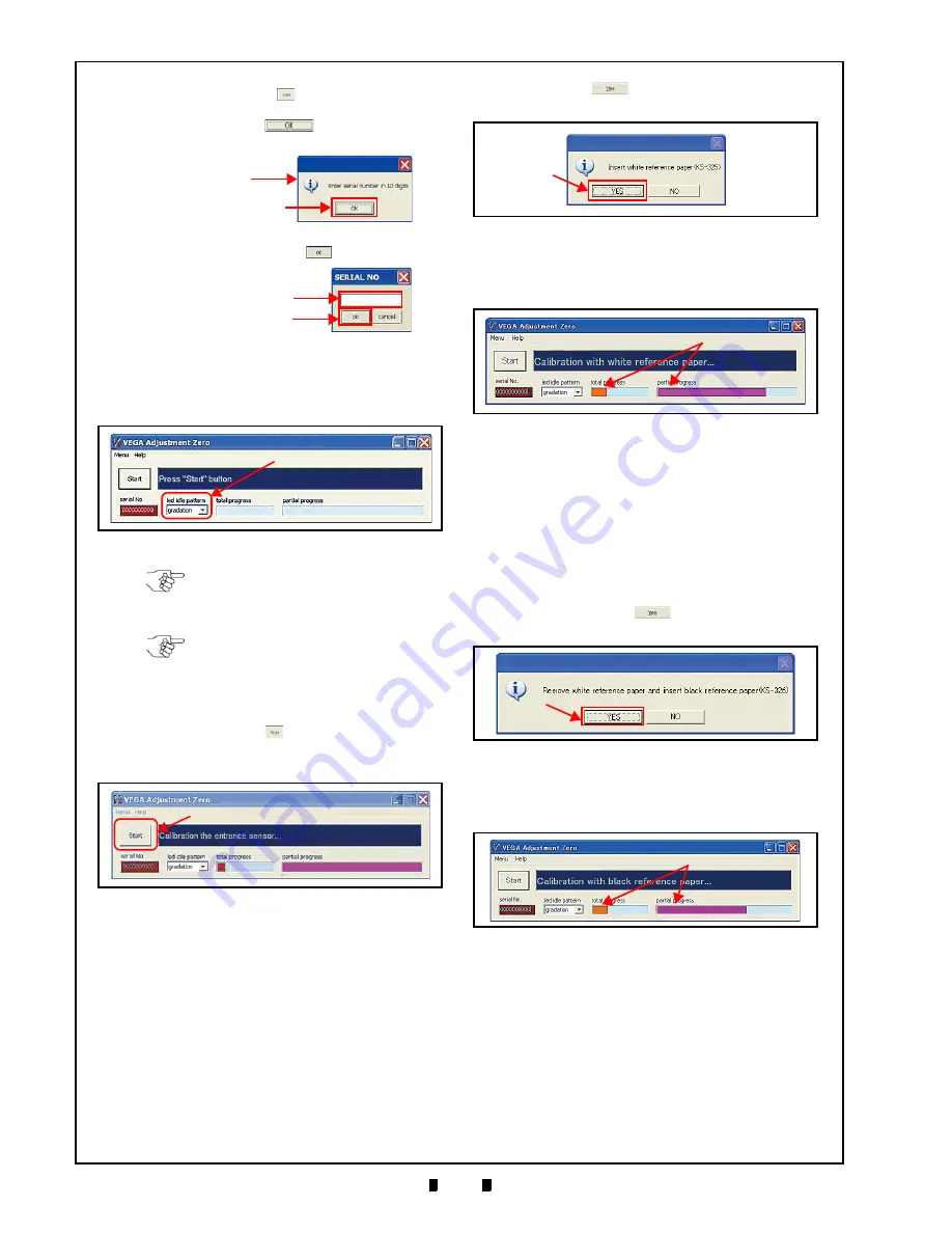
10. Set the Standby Mode Front Panel LED Display
Color pattern by choosing the desired pattern
from the three (3) selections available in the “
led
idle pattern
” Pull-down Menu (Figure 6-37
a
).
11. Click on the “
Start
”
Button to begin the
Entrance Sensor Calibration Procedure
a
).
12. When the Entrance Sensor Calibration is com-
plete, the White Reference paper Setting Dialog
will appear (Figure 6-39).
13. Set the White Reference Paper in place (See
“Reference Paper Usage” on page 6-4).
14. Click “
Yes
”
Button (Figure 6-39
a
) to
begin the White Reference Paper Calibration.
15. Confirm the Test progress by checking the
Progress Bar (Figure 6-40
a
).
16. Once the White Reference Paper Calibration
procedure is compete, the “Remove white
reference paper and insert black reference paper
(KS-326)” Dialog Message (Figure 6-41) will
appear.
Remove the White Reference Paper from the
Transport Section and insert the Black Reference
Paper.
17. Click on the “
Yes
”
Button (Figure 6-41
a
)
to begin the Black Reference paper Calibration.
18. Confirm the Test progress by checking the
Progress Bar (Figure 6-42
a
).
19. Once the Black Reference Paper Calibration
procedure is complete, the “Remove black
reference paper” Dialog Message (Figure 6-43)
will appear.
Remove the Black Reference Paper.
If clicking the “
Start
”
Button before a Serial
Number is entered, the Dialog Message will
appear. Click “
OK
”
Button to call the
“
SERIAL NO
” Text Input Dialog Window.
Type the Serial Number into the Text Input
Field and then click “
OK
” Button.
OK Button
Dialog Message
OK Button
Text Input Field
Figure 6-37
LED Idle Pattern Menu Location
a
Figure 6-37
LED Idle Pattern Menu Location
NOTE: The Standby indication can
also be set by DIP Switch (See “LED
Pattern Setting Mode” on page 2-3).
NOTE: Unless a complete setup
Mode Color selection result is saved
in EEPROM, the VEGA Unit will not
be able to decide Standby Color
selection.
Figure 6-38
a
Figure 6-38
Entrance Sensor Calibration
a
Figure 6-39
White Reference paper Placement
Request Dialog
Figure 6-40
White Reference Paper Calibra-
a
Figure 6-40
White Reference Paper Calibration
Progress Screen
a
Figure 6-41
Black Reference Paper Placement
Request Dialog Screen
Black Reference Paper Calibra-
a
Figure 6-42
Black Reference Paper Calibration
Progress Screen


