background image

© 2019 JCM Global Corporation

3

Part No. 960-000207R_Rev. A

TBV™-100/101 Units

TBV Unit is 

not working. 

(The CPU Board’s 

RED

 LED is lit.)

RAM Malfunction

Check TBV Harness and Connectors 

are properly connected. 

Replace the CPU Board.

TBV Unit is 

not working. 

(Fan motor cycles 

ON and OFF 

alternately.)

ROM Malfunction

Check TBV Harness and Connectors 

are properly connected. 

Replace the CPU Board.

TBV Unit is not 

working. Banknote 

Jam occurred. 

(The TBV Bezel

LED is flashing 

RED

 or 

YELLOW

.)

TBV Setting 

malfunction. An 

improper Assembly 

and/or Harness 

connection exists.

A Banknote Jam or 

foreign object is in 

the Banknote path.

Check the TBV assembly and 

connections are correct. 

Check for a Banknote jam or foreign 

object in the Banknote transport 

path. 

Check that the LED flashing pattern 

is correct and identify the indicated 

error by referring to the Error Codes 

tables.

Most Banknotes 

are rejected. (The 

TBV Bezel LED is 

flashing 

GREEN

.)

The current 

Firmware is not 

correct for the 

inserted Banknotes.

Check that the acceptable 

denomination values are correct. 

Download the correct Firmware.

DIP Switch Settings 

are incorrect.

Check that the DIP Switch Settings 

are properly set.

Banknote accept/

inhibit setting is 

being made by 

command from the 

Host Machine.

Check that the Host commands are 

correct.

Dirt or foreign 

objects are adhering 

to the Sensors.

Clean the Sensors.

Improper validation 

process 

performance. 

Improper assembly 

and/or Harness 

connection. CPU 

Board and/or Sensor 

are malfunctioning.

Check that all assembly and 

connections are properly set. 

Identify the LED Error Code flashing 

pattern and identify the error. 

Refer to the Error Code Tables.
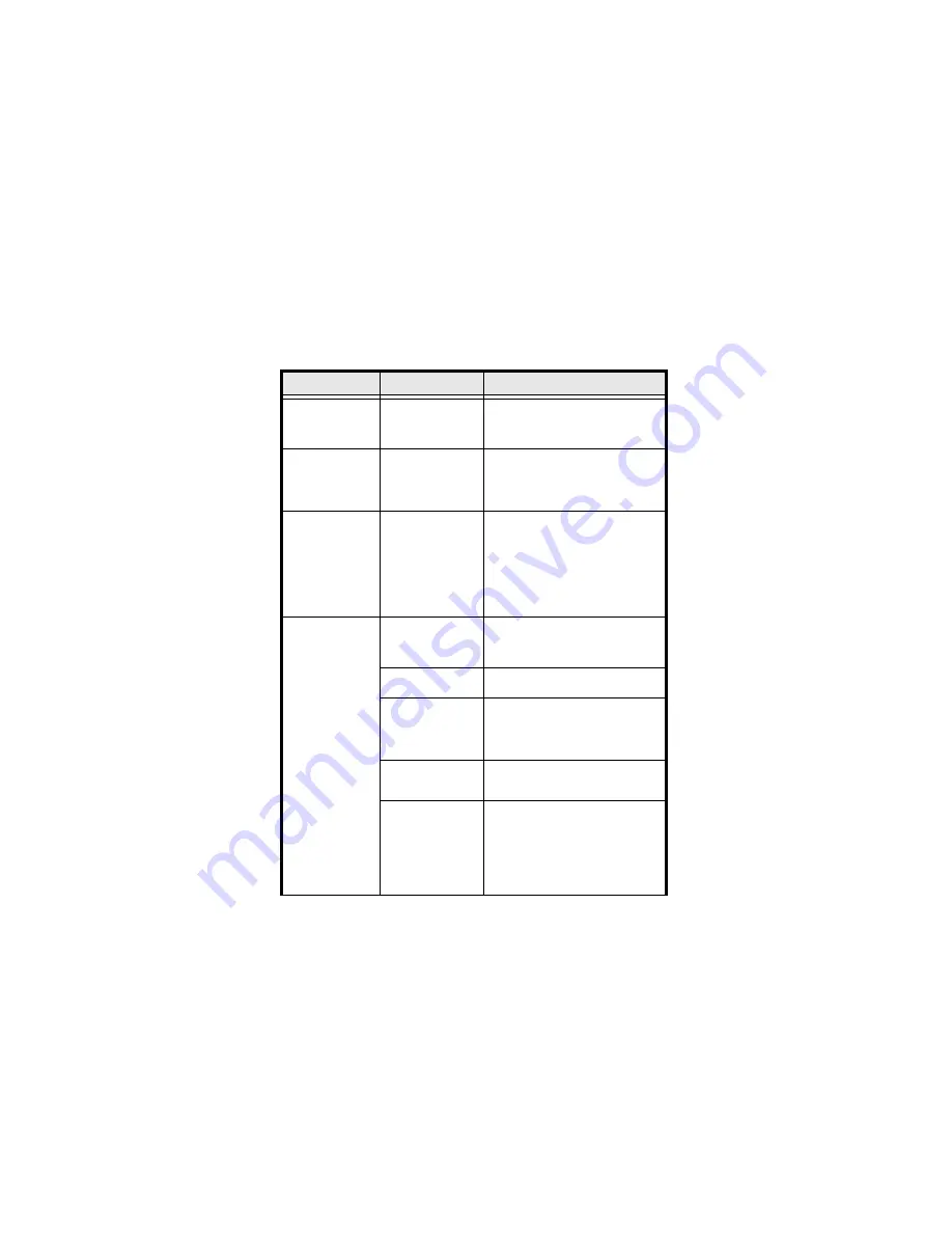
Table 2 

TBV Troubleshooting Descriptions

Issue

Probable Cause

Possible Solutions

Summary of Contents for TBV-100 FSH

Page 1: ...ting methods please contact the Technical Support Division of Customer Service via the email addresses listed below Americas support jcmglobal com Europe Middle East Africa Russia support jcmglobal eu...

Page 2: ...th TBV 101 GSH Single note Gated Bezel Horizontal Stack Cash Box Fixed Path TBV 101 ASH Single note JCM Standard Bezel Horizontal Stack Cash Box Fixed Path Table 2 TBV Troubleshooting Descriptions Iss...

Page 3: ...ashing pattern is correct and identify the indicated error by referring to the Error Codes tables Most Banknotes are rejected The TBV Bezel LED is flashing GREEN The current Firmware is not correct fo...

Page 4: ...to the specific Country s Software Information Sheet Foreign objects are adhering to the sensors Clean the Sensors Need to perform Sensor Calibration Did not perform Sensor Calibration after the Unit...

Page 5: ...CEPT 2 VEND 2 INHIBIT VEND 2 ACCEPT 3 VEND 3 INHIBIT VEND 3 ACCEPT 4 VEND 4 INHIBIT VEND 4 ACCEPT 5 VEND 5 INHIBIT VEND 5 ACCEPT 6 VEND 6 INHIBIT VEND 6 ACCEPT 7 VEND 7 INHIBIT VEND 7 ACCEPT 8 N A N A...

Page 6: ...oupon Checksum may need to be changed for improved reading accuracy For higher reliability and read accuracy the Double Read Setting is recommended for use with the TBV Validation System Barcode Coupo...

Page 7: ...cessing validation or an INHIBIT Command Yellow Flashes Internal processing Self download Transport section BNF Section Yellow Flashes Returns to Standby Mode after clearing the error condition See St...

Page 8: ...ons are accessible from the JCM Tool Suite Service Mode Options menu refer to Figure 2 and Table 8 When the TBV Unit is in Test Mode and DIP Switch DS1 or DS3 Switch 8 is ON The TBV Status LED Indicat...

Page 9: ...Purpose Operational Mode Download Update TBV Unit Firmware Statistics Check Banknote Ticket Acceptance and any Error Status that may occur Event Log View Display Historical Activity on the TBV Unit Te...

Page 10: ...ropriate TBV Firmware file from Windows Explorer 5 Click the Download button Figure 3 b to start the Download Download progress is shown by a progress barograph and a percentage complete indication lo...

Page 11: ...t in Forced Download mode with DS1 or DS3 Switches 1 6 7 and 8 ON 3 Reapply Power to the TBV Unit 4 Connect the BlueWave 2 0 DT 200 Unit to the TBV Unit Figure 4 a using a Male A to mini B USB cable 5...

Page 12: ...nit using a Male A to mini B USB Cable Figure 5 a 3 Slide the BlueWaveDX Power switch ON Figure 5 b 4 From the Firmware menu press the OK button Figure 5 c 5 Scroll through the TBV Firmware versions t...

Page 13: ...Connect the TBV Unit to the PC s USB port using a Male A to mini B USB Cable 4 From the JCM Tool Suite Application Service Mode drop down menu refer to Figure 2 click on Performance Test 5 Click on th...

Page 14: ...Test click the STOP button Figure 7 Opening TBV Transport Guide Rear 85 Section NOTE The Judgement Validation Sensor is not interactive To test it 1 Power off the TBV Unit then remove and rotate the...

Page 15: ...or Positioning Sensor 1 Click on the JCM Tool Suite Service Mode drop down menu refer to Figure 2 then click on Sensor Adjustment 2 Click the Validation Sensor or Positioning Sensor radio button Figur...

Page 16: ...shes Error Type Cause 1 Banknote Jam in Cash Box When transporting Banknotes to the Cash Box Sensors did not detect the correct number of Banknotes 2 Banknote Jam in Transport Section When transportin...

Page 17: ...bnormal movement 6 Shutter Error Shutter Sensors detected abnormal movement 7 Banknote Jam Pusher Mechanism Pusher Mechanism home sensor is not detected 8 Pusher Mechanism Home Sensor The Pusher Home...

Page 18: ...g is abnormal 20 EEPROM Writing EEPROM writing is abnormal 21 Feed Motor Over Current Improper current level detected while Feed Motor is active 22 Stacker Motor Over Current Improper current level de...

Page 19: ...detects an abnormal Banknote type 9 INHIBIT Setting Banknote accept inhibit setting made by a command from the Host 10 Reject Command Reject command received from the Host 11 Cash Box Removed Sensor d...

Page 20: ...Value non Paper 16 digits 01 YYYY YYYY YYYY YYYY Refer to Table A 6 and A 7 in the TBV Series Transaction Based Validator Operation and Maintenance Man ual JCM Part No 960 100926R for Sensor Flag Val...

Page 21: ...0 10 BOX_NFUL Box Near Full Sensor 00 00 20 STK_HOM Pusher Plate Home Position Sensor 00 00 40 STK_HAF Pusher Plate Half way Position Sensor 00 00 80 BOX_IN Box Sensor 00 01 00 WID_HOM Centering Mecha...

Page 22: ..._irl_ref 0000 0000 0000 0040 dr_ir_ref 0000 0000 0000 0080 dc_irr_ref 0000 0000 0000 0100 dll_gre_ref 0000 0000 0000 0200 dc_redr_ref 0000 0000 0000 0400 drr_gre_ref 0000 0000 0000 0800 ull_ore_ref 00...

Page 23: ...0000 0008 0000 0000 dl_ore_pen 0000 0010 0000 0000 do_redr_pen 0000 0020 0000 0000 dr_ore_pen 0000 0040 0000 0000 drr_gre_pen 0000 0080 0000 0000 ull_ore_pen 0000 0100 0000 0000 ul_blu_pen 0000 0200 0...

Page 24: ...lean dry lint free Micro fiber cloth If necessary use a mild non abrasive detergent mixed with water to clean the Sensors Wipe off any excess moisture from the TBV Unit s surfaces CASH BOX PREVENTIVE...

Page 25: ...M Europe GmbH M endelheimer Weg 60 D 40472 D esseldorf Germany Phone 49 211 530 645 60 Fax 49 211 530 645 85 Email support jcmglobal eu UK Ireland JCM Europe UK Office Unit B Third Avenue Denbigh West...

Page 26: ...0 Fax 1 702 644 5512 Email support jcmglobal com Asia and Oceania JCM Gold HK Ltd Unit 1 7 3 F Favor Industrial Centre 2 6 Kin Hong Street Kwai Chung N T Hong Kong Phone 852 2429 7187 Fax 852 2929 700...

Reviews:

Related manuals for TBV-100 FSH