6 - 2
Checking the Slew Gearbox Oil Level
1. Prepare the Machine
Position the machine on level ground. Stop the engine
and remove the starter key.
2. Locate the Slew Gearbox
See C
omponent Location Diagrams
at the end of this
section.
3. Check the Level
a.
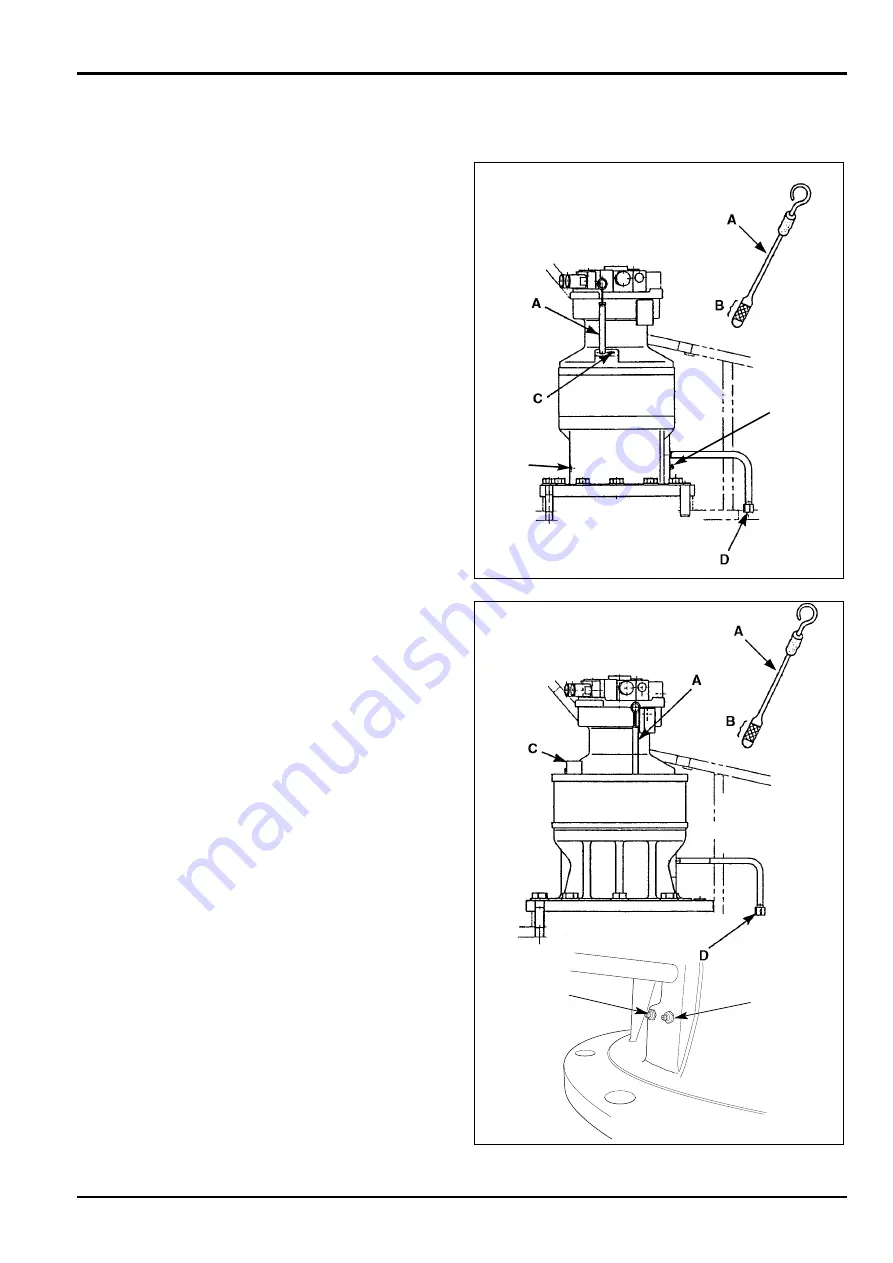
Remove the dipstick
A
, wipe it clean and re-fit.
b.
Remove the dipstick again and check that the oil
level is within the range
B.
c.
If necessary, top up through filler port
C
.
(See
Lubricants and Capacities
for oil type)
.
4. Refit the Dipstick.
Changing the Slew Gearbox Oil
1. Prepare the Machine
Position the machine on level ground. Stop the engine
and remove the starter key.
2. Drain the Oil
a.
Remove the drain plug
D
. Allow the oil to drain out.
b.
Wipe the drain plug clean. Remove any metallic
particles, if foreign matter is found, contact local
dealer.
c.
Refit the drain plug. Make sure it is tight.
3. Fill with New Oil
See
Lubricants and Capacities
for oil type and volume.
Fill with new oil through filler port
C
until it reaches the
full mark on the dipstick when settled. refit the dipstick.
4. Check for Leaks
Run the machine, operate the slew controls and make
sure there are no leaks.
Replenishing Slew Gearbox Grease
1. Prepare the Machine
Position the machine on level ground. Stop the engine
and remove the starter key.
2. Remove Air Bleed Plug E.
!
!
CAUTION
Failure to remove the bleed plug before adding grease
could damage the inner seal.
8-3-4-7
3. Fill Up with Grease
See
Lubricants and Capacities
for grease type.
Pump in grease through nipple
F
until the grease starts
to ooze from bleed plug
E
. Refit and tighten the bleed
plug.
On later machines, the slew gearbox bearing (normally
lubricated at point
F
has changed to a sealed for life type
bearing and no longer requires lubrication.
Note:
All machines that have a grease nipple at
F
still require
lubricating every 1000 hours.
Section 3
Routine Maintenance
9803/6400
Section 3
6 - 2
Issue 2*
Transmission
(continued)
*JS200/JS210/JS220
*JS240/JS260
E
F
*
F
E
Summary of Contents for JS 200 Series
Page 57: ...9 1 Section 3 Routine Maintenance 9803 6400 Section 3 9 1 Issue 2 Component Location Diagram...
Page 113: ......
Page 137: ...5 3 Section C Electrics 9803 6400 Section C 5 3 Issue 2 Pump Control FLOW CHART...
Page 201: ...10 7 Section C Electrics 9803 6400 Section C 10 7 Issue 1 CAPs II Diagnostic system K C...
Page 215: ...Section E Section E Hydraulics 9803 6400 Issue 2 3 2 3 2 Schematics...
Page 217: ...Section E Section E 9803 6400 Issue 2 3 3 3 3 Hydraulics Schematics...
Page 218: ...3 5 Section E Hydraulics 9803 6400 Section E 3 5 Issue 1 Schematics Shuttle Block JS200 JS240...
Page 232: ...10 1 Section E Hydraulics 9803 6400 Section E 10 1 Issue 1 Hydraulic Pump JS200 JS240...
Page 233: ...10 2 Section E Hydraulics 9803 6400 Section E 10 2 Issue 1 Hydraulic Pump JS200 JS240...
Page 234: ...10 3 Section E Hydraulics 9803 6400 Section E 10 3 Issue 1 Hydraulic Pump JS200 JS240...
Page 263: ...30 2 Section E Hydraulics 9803 6400 Section E 30 2 Issue 1 Control Valve JS200 JS240...
Page 264: ...30 3 Section E Hydraulics 9803 6400 Section E 30 3 Issue 1 Control Valve JS200 JS240...
Page 265: ...30 4 Section E Hydraulics 9803 6400 Section E 30 4 Issue 1 Control Valve JS200 JS240...
Page 266: ...30 5 Section E Hydraulics 9803 6400 Section E 30 5 Issue 1 Control Valve JS200 JS240...
Page 267: ...30 6 Section E Hydraulics 9803 6400 Section E 30 6 Issue 1 Control Valve JS200 JS240...
Page 268: ...30 7 Section E Hydraulics 9803 6400 Section E 30 7 Issue 1 Control Valve JS200 JS240...
Page 327: ...51 12 Section E Hydraulics 9803 6400 Section E 51 12 Issue 1 Solenoid Valve 8 spool...
Page 328: ...55 1 Schematic Section E Hydraulics 9803 6400 Section E 55 1 Issue 1 Shuttle Valve...
Page 330: ...55 3 Schematic Section E Hydraulics 9803 6400 Section E 55 3 Issue 1 Cushion Valves...
Page 481: ...7 15 Section F Transmission 9803 6400 Section F 7 15 Issue 2 Motor...
Page 482: ...7 16 Section F Transmission 9803 6400 Section F 7 16 Issue 1 Motor...


