19C-1E
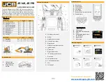
QUICK REFERENCE GUIDE
This Quick Reference Guide DOES NOT replace the Operators
Manual. You MUST read ALL the disclaimers and safety and other
instructions in the Operators Manual before initially operating this
product. Accordingly, no legal claims can be entertained based on
the data, illustrations or descriptions in this Quick Reference Guide.
Access additional information
Instrument Panel
Start Up Sequence
Static Dimensions
Tie Down Points
Cab and Switch Panel
A. Track controls
B. Control Lever
C. Track extension lever
D. Dozer blade control lever
E.
Ignition Switch
F.
Motor running indicator light
G. Rotary hand throttle control
H. Instrument panel
J.
Console switch panel
K. Auxiliary power socket
L.
Fire extinguisher
M. Operator seat
N. Control isolation lever
O. Charging cable stowage
P.
Quickhitch release bar
stowage
Cab
Switch Panel
A. Front undercarriage track leg tie-down points
B. Rear undercarriage track leg tie-down points
C. Angle = 25º to 45º
D. Angle = 9º to 15º
E.
Length = 8’ 2”
F.
Length = 5’ 8” to 3’ 4”
G.
Length = 8’ 2”
H. Slew ring center line
J.
Tie down decal
A. Control Isolation Switch (2Go)
B. Aux 1 selection switch
C. Lift overload on/off switch
D. Work lights on/off switch
E.
Wipers/washer on/off switch
F.
Auto-hydraulic warming switch (not used)
G. H+ mode selection switch (not used)
H. Aux 2 selection switch
J.
Auto idle on/off switch (not used)
K. Beacon on/off switch
L.
Q-hitch sequence
A. Battery Level
indicator gauge
B. Warning and
indicator lamps
Lifting Points
A. Boom Lift Point
B. Dozer Blade Lift Point
C. Spreader Bar
D. Centre of Gravity
E.
2’ 8”
F.
2’ 7”
G.
1’ 9”
Revision 1.0
1/11/2021


