background image

16

21-18AG

Instruction & User Manual

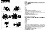
Auxiliary Handle


m

Choose the position that provides the most 
comfortable and safest handling. Screw the 
auxiliary handle onto the top, left or right of 
the machine head as required.

Guard


m

Fit the guard as shown in the illustration. 
Adjust the clamping force of the locking arm 
by tightening the hex screw out or in when 
the locking arm is unloaded.

Changing Grinding Discs

To remove an attached disc:


m

Press down the spindle lock button (3).


m

Lift up the release tab on the tool free 
locking nut (5). Turn anti-clockwise to 
release.


m

Slowly rotate the grinding disc manually 
while holding in the spindle lock button.


m

Make sure the spindle lock button engages 
into the shaft during slow rotation of the 
grinding disc.”


m

Unscrew the tool free locking nut (5) from 
the output shaft, loosening the grinding 
wheel (6).


m

Remove the grinding wheel from the lower 
plate (7).


m

If storing the angle grinder without a disc, 
reinstall the tool free locking nut (5).

To attach a new disc:


m

Align the flats on the lower plate (7) with the 
flats on the output shaft.


m

Place the grinding wheel (6) on the lower 
plate, carefully checking the boss of the 
lower plate fits securely in the mounting 
hole of the grinding disc.


m

Screw the tool free locking nut (5) onto the 
output shaft, on top of the grinding wheel, 
carefully checking the boss of the locking 
nut fits securely in the mounting hole of the 
grinding disc.


m

 Press down the spindle lock button (3) 
while slowly manually turning the new 
grinding disc until the spindle lock fully 
engages in the output shaft.


m

Use the tab on the tool free locking nut (5) 
to fully tighten.


m

Release the spindle lock button once the 
locking nut is fully tightened.

 During all work undertaken with the tool, 
the auxiliary handle must be mounted.

WARNING!

Switch off the tool and disconnect the power 
(remove battery/unplug as  appropriate) 
before changing grinding discs.

WARNING!

Grinding and cutting discs become very hot 
while working; do not touch until they have 
cooled & always use gloves.

Pay attention to the dimensions of the 
grinding disc. The mounting hole diameter 
must fit the lower plate without play. Do not 
use reducers or adapters.

Actuate the spindle lock button only when 
the grinder output shaft is at a standstill.

NOTE

Check the direction of rotation of the 
accessory matches the direction of rotation 
marked on the power tool!

NOTE

Summary of Contents for 21-18AG

Page 1: ...POWER TOOL INSTRUCTION USER MANUAL EN 21 18AG Original Instructions IM 18AG EN Iss 11 2022...

Page 2: ...ctronic waste The product should not be discarded with household waste but must be returned to a collection system which conforms to the EU Directive 2012 19 EU or the UK Waste Electrical and Electron...

Page 3: ...ckback And Related Warnings 9 CHARGER SAFETY 11 COMPONENT LIST 12 POWER TOOL TECHNICAL DATA 13 LITHIUM ION BATTERY TECHNICAL DATA 13 CHARGER TECHNICAL DATA 13 NOISE INFORMATION 13 VIBRATION INFORMATIO...

Page 4: ...t conditions Water entering a power tool will increase the risk of electric shock m Do not abuse the cord Never use the cord for carrying pulling or unplugging the power tool Keep the cord away from h...

Page 5: ...stments changing accessories or storing power tools Such preventive safety measures reduce the risk of starting the power tool accidentally m Store idle power tools out of the reach of children and do...

Page 6: ...d or modified batteries may exhibit unpredictable behaviour resulting in fire an explosion or risk of injury m Do not expose a battery pack or tool to fire or excessive temperature Exposure to fire or...

Page 7: ...ess a fully enclosed blade guard is fitted Operations for which the power tool was not designed may create a hazard and cause personal injury m Do not use accessories which are not specifically design...

Page 8: ...nd may cause loss of control m Do not use a damaged accessory Before each use inspect the accessory such as abrasive wheels for chips and cracks backing pad for cracks tear or excess wear wire brush f...

Page 9: ...sudden reaction to a pinched or snagged rotating wheel backing pad brush or any other accessory Pinching or snagging causes rapid stalling of the rotating accessory which in turn causes the uncontrol...

Page 10: ...wheel s movement at the point of snagging m Use special care when working corners sharp edges etc Avoid bouncing and snagging the accessory Corners sharp edges or bouncing have a tendency to snag the...

Page 11: ...ged cord or plug Have them replaced immediately m JCB battery chargers are designed to operate on 230 240V AC input voltage Note the dual charger can additionally operate on 100 240 AC input voltage D...

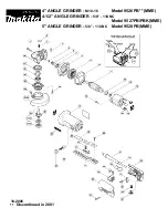
Page 12: ...PINDLE LOCK 4 ADJUSTABLE GUARD 5 TOOL FREE LOCKING NUT 6 GRINDING DISC 7 LOWER PLATE 8 BATTERY RELEASE BUTTON 9 CHARGER 10 BATTERY PACK PLEASE REFER TO TABLE ON PAGE 13 FOR BATTERY INFORMATION 11 BATT...

Page 13: ...utput 21 18VFC 220 240V AC 50 60Hz 70W 14 4 18V d c 2 4A 21 18VSFC 220 240V AC 50 60Hz 105W 14 4 18V d c 4 0A 21 18VDC 100 240V AC 50 60Hz 200W 20 5V d c 2 x 3 5A CHARGER TECHNICAL DATA LITHIUM ION BA...

Page 14: ...WAYS use sharp chisels drills and blades m Maintain this tool in accordance with these instructions and keep well lubricated where appropriate m If the tool is to be used regularly then invest in anti...

Page 15: ...this charging and discharging cycle 4 to 5 times to ensure battery is correctly conditioned WARNING m Place the battery charger on a level and stable surface Plug the charger into a suitable power poi...

Page 16: ...nding wheel 6 on the lower plate carefully checking the boss of the lower plate fits securely in the mounting hole of the grinding disc m Screw the tool free locking nut 5 onto the output shaft on top...

Page 17: ...g the pressure release function of the ON OFF Trigger gives you added safety Letting go will make the power tool stop itself NOTE Surface Grinding m Allow the power tool to reach full speed before tou...
Page 18: ...ng the angle of the cut will cause the wheel to bend and may cause wheel breakage Edge grinding wheels are not designed to withstand side pressures caused by bending m Remove the power tool from the w...

Page 19: ...r can service or repair Never try to repair the power tool yourself Take to an authorised service centre WARNING Transport and Storage m If the power tool will remain unused for any length of time it...

Page 20: ...ificate together with the original sales receipt will be required in the event of any claim within the warranty period Should you choose not to register your product within 30 days of purchase your st...

Page 21: ...elops a fault within 30 days of purchase return it to the retailer where it was purchased together with your sales receipt If a product develops a fault after 30 days a warranty claim must be submitte...

Page 22: ...tion UK Authorised Representative Service 77 Camden Street Lower EU DECLARATION OF CONFORMITY SIGNATURE FUNCTION PRODUCT S COVERED BY THIS DECLARATION 4 IDENTIFICATION DETAILS OF MANUFACTURER 1 6 REFE...
Reviews: