background image

7

+4dBV (switch IN) or -10dBu (switch OUT) to match the nominal level of the 
signal source.  If you don’t know how to set the switch, consult the documentation 
for the signal source.  Most professional devices operate at +4dBV while most 
consumer devices operate at -10dBu.  (See page 23 in this manual for  audio con-
nections and wiring diagram.)


Do 

NOT

 make connections to both the XLR and ¼� analog connectors; use one or  

the other.

b.  If you are connecting digital signals (i.e., from a digital console or workstation, 

or from the digital outputs of a CD or DVD player or processor), use appropriate 
cabling to make a connection between the device and the rear panel AES/EBU 
(XLR) or S/PDIF (phono) input of the speaker designated to carry the LEFT  
channel (i.e., the left speaker in a stereo setup).  Then use appropriate cabling to 
make a connection between the rear panel AES/EBU (XLR) or S/PDIF (phono) 
output of the left speaker and the rear panel AES/EBU or S/PDIF input of the 
speaker designated to carry the RIGHT channel (i.e., the right speaker in a stereo 
setup).  (See page 24 in this manual for a wiring diagram.)


When using digital audio inputs, the rear panel DIP switch settings determine which 

channel of the stereo AES/EBU or S/PDIF signal will be reproduced by each speaker.
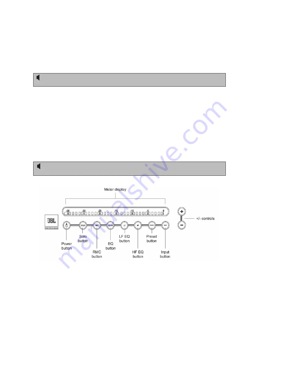
 

LSR4300 Front Panel

7.  Press the front panel INPUT button on any speaker so that it begins blinking.  While it is 

still blinking, press the + / - controls on any speaker to select the desired input.  The front 
panel LEDs and the rear panel ACTIVE INPUT display shows which of the three inputs 
(Analog, S/PDIF, or AES/EBU) is currently selected.  If a digital input is selected, the rear 
panel ACTIVE INPUT display also shows which channel is being reproduced by  
that speaker.  

Quick Start

Summary of Contents for LSR4300

Page 1: ...LSR4328P LSR4326P Studio Monitors Owner s Manual ...

Page 2: ...ii ...

Page 3: ...n into the apparatus the apparatus has been exposed to rain or moisture does not operate normally or has been dropped 15 The appliance coupler of the power supply cord is used as the ultimate disconnect device from the mains The appliance coupler shall remain readily operable 16 The apparatus shall be connected to mains socket outlet with a protective earthing connection Explanation of Graphic Sym...

Page 4: ...ion 24 Performing An RMC Calibration 25 Equalization 28 Restoring Factory Settings 30 LSR4300 Control Center Software 30 Appendix A EQ Presets 31 Appendix B System Block Diagram 33 Appendix C Wiring Requirements 34 Appendix D Mounting Specifications 37 Appendix E SPL Calibration 38 Appendix F Error Messages and Troubleshooting 39 Appendix G Important Information About LSR4300 Firmware 41 Specificati...

Page 5: ... Once you ve got your LSR4300 system powered up and delivering sound you should turn to the Reference section which describes every feature and function of the LSR4300 in detail Finally we ve included a number of technical appendices and specifications at the end of this manual Note that this manual covers the model LSR4328P and LSR4326P Studio Monitors Separate owner s manuals are provided for the...

Page 6: ...ent or worse yet lack of any treatment at all can result in anomalies such as resonant frequencies and low frequency standing waves the aural equivalent to the lens being smeared Trying to create a mix in such an environment can be as frustrating and difficult as trying to paint a masterpiece while blindfolded JBL s exclusive second generation RMC Room Mode Correction technology is designed to solv...

Page 7: ...d HiQNet automatically aligns the entire system setting relative volume so that the sound from all channels is balanced when it arrives at the mix position The end result is precise imaging regardless of each monitor s actual physical placement In addition the ability to centrally control the volume of all the speakers via the supplied wireless remote control or LSR4300 Control Center software is ...

Page 8: ...r All transducers are self shielded with Neodymium motor structures for exceptional transient response and superb power handling Advanced front panel user interface allows control of system functions such as volume input selection user EQ and EQ presets RMC calibration and bypass individual speaker solo and brightness level of the meter and buttons Front panel meters show continuous output levels ...

Page 9: ...teries Here are simple step by step instructions to get you up and running quickly 1 Unpack the speakers To avoid damage to the speaker elements open the top of the box keep the Styrofoam end cap on and roll the box upside down The box can then be slipped off This also works in reverse for repacking the units Be sure to not grasp the monitors from the front A stray hand or finger can cause damage t...

Page 10: ... up ON position for the speaker reproducing the left channel and place the DIP switch labeled RIGHT in the up ON position for the speaker reproducing the right channel See page 22 in this manual for more information Make sure that one and only one DIP switch is placed in the up ON position for each speaker One speaker in the system must have the LEFT DIP switch set to the ON position 6 Make all re...

Page 11: ...ereo setup Then use appropriate cabling to make a connection between the rear panel AES EBU XLR or S PDIF phono output of the left speaker and the rear panel AES EBU or S PDIF input of the speaker designated to carry the RIGHT channel i e the right speaker in a stereo setup See page 24 in this manual for a wiring diagram When using digital audio inputs the rear panel DIP switch settings determine ...

Page 12: ...ton on any speaker then walk to a spot in the room where you are not blocking the path between the microphone and any speaker Each speaker will emit a reference tone in turn and its meter will show a left to right chase pattern that indicates the system is calibrating When the chase pattern on the meters stops the process is complete You can compare the effects of RMC with the uncorrected response...

Page 13: ... AC power source indicating the speaker is in standby status It is illuminated at full brightness when the speaker is powered up and active Full brightness level is variable set using the brightness level function on the front panel remote control or LSR4300 Control Center Software The JBL logo flashes to indicate the following conditions DIM function is engaged using the Remote Control or LSR4300 ...

Page 14: ...Overall system volume see 11 below Meter and button brightness see 11 below Error conditions The meter has 31 three color segments that can illuminate in green amber or red For many of the above operations all 31 segments light green only However when audio signal is being reproduced by the speaker all three colors are used and the meter is calibrated to indicate the continuous output in decibels ...

Page 15: ...meter segments will flash to indicate a muted state To end solo and unmute all other networked speakers press the SOLO button for that speaker again All front panel button actions can be cancelled at any time simply by pressing the button a second time 5 RMC Room Mode Correction This button is used both to initiate an RMC calibration and to bypass it after it has been performed in order to compare ...

Page 16: ...n to activate LF EQ it will flash While flashing press the button to increase the amount of LF EQ in 0 25 dB steps or press the button to decrease the amount of LF EQ in 0 25 dB steps For more information see page 28 in this manual Once set the LF and EQ buttons will remain illuminated to indicate that LF equalization has been applied 8 HF High Frequency boost cut Allows you to apply 2 dB of high fr...

Page 17: ... select and activate one of six factory EQ presets or a seventh current setting preset To recall a preset press the PRESET button It will flash While flashing use the or buttons to select the desired preset Reference Front Panel ...

Page 18: ...ght goes out or by manually setting both the LF and HF values to 0 dB 10 INPUT Input Select Allows you to listen to any of three connected signal sources analog S PDIF digital or AES EBU digital To select an input source press the INPUT button It will flash and the meter display will confirm the currently selected input source In addition incoming signal will temporarily be muted While the INPUT but...

Page 19: ...indicate the current selection When monitoring digital S PDIF or AES EBU signal the rear panel DIP switches must be set correctly in order to determine which channel is being reproduced For more information see page 23 in this manual If you select a digital input to which no signal is connected no signal will be heard and the left most meter segment will flash to indicate an error condition Referen...

Page 20: ...nd the Meter Display There are six settings at the lowest setting all buttons and meter segments are completely off and only the JBL logo glows to indicate power Rear Panel LSR4328P LSR4326P Rear Panel 1 Input Sensitivity switch In the OUT position selects 10 dBV sensitivity for the analog input In the IN position pressed in selects 4 dBu sensitivity for the analog input 2 Analog XLR Balanced inpu...

Page 21: ...nnection when using the provided LSR4300 Control Center software 11 DIP switches These eight switches are used to identify the channel being carried by each speaker in a networked system If one of the two digital inputs is being monitored the DIP switch setting also determines whether the speaker is reproducing the left Channel A or right Channel B side of the incoming stereo signal In normal oper...

Page 22: ... as power on volume adjust soloing input select EQ adjustment and preset selection and adds the following extra functions A dedicated brightness control System volume DIM function When a function is selected using the remote control the corresponding indicator on the speaker front panel illuminates to confirm the selection Reference Remote Control 1 2 3 7 8 5 4 4 6 9 LSR4300 Remote Control Earlier ...

Page 23: ...peaker 6 EQ controls a EQ ON Duplicates the function of the front panel EQ control b HF Duplicates the function of the front panel HF control c LF Duplicates the function of the front panel LF control d PRESET Duplicates the function of the front panel PRESET control After pressing any of the EQ controls on the remote control be sure to press the Volume control afterwards in order to make any requ...

Page 24: ... they should be placed on suitable speaker stands and well away from boundaries such as walls ceilings and large pieces of furniture The LSR4328P and LSR4326P are equipped with mounting points to allow wall and ceiling mounting using industry standard mounting hardware See Appendix D on page 37 in this manual for details LSR4300 Series monitors are designed to be positioned vertically and not hori...

Page 25: ...single button with the supplied calibration microphone connected to a single speaker It also makes it possible for all speakers in the system to be controlled using the supplied wireless remote control and or LSR4300 Control Center Software Up to eight LSR4328P or LSR4326P speakers can be interconnected in a single network HiQnet enables coordinated RMC calibration so sound arriving at the mix pos...

Page 26: ...ve its LEFT DIP switch set to ON When using only a single speaker set the LEFT DIP switch to ON regardless of the speaker s physical position in the room If required LSR4300 monitors can be used without being networked together i e without any CAT5 cable interconnections In this case the LEFT DIP switch in every speaker must be set to the ON position and all other DIP switches in every speaker mus...

Page 27: ...ain the output acoustic level of 94 dB SPL at a distance of one meter Use of the front panel Volume control that is pressing the button when no button is flashing allows further level matching Incoming analog signal is internally routed to the LSR4300 s high resolution 96kHz 24 bit oversampling A D converters Digital Connections Connect digital sources in AES EBU format to the rear panel XLR digita...

Page 28: ...BU connections and 75 ohm cabling for S PDIF connections LSR4300 audio interconnections RMC Room Mode Correction When a loudspeaker is placed in any work space it and the room behave as a system which for better or worse acts as the reference point for creative decisions When a room has inadequate or incorrect acoustic treatment room modes sometimes called standing waves can result producing low f...

Page 29: ...arly useful in surround sound applications where space limitations often prevent optimum speaker placement For example if the center speaker is closer to the mix position than the other main speakers attenuation must be applied so your mix balances are correct Without this correction your end product will sound unbalanced on a properly calibrated playback system Performing An RMC Calibration To ge...

Page 30: ...rom the nearest speaker Position the calibration microphone vertically 3 Connect the microphone to the Left speaker s rear panel RMC MIC input To perform RMC the calibration microphone must be connected to the speaker designated as Left LEFT DIP switch up 4 Press and hold the RMC button on any speaker for at least 3 seconds until the RMC light on the front panel of all speakers begins blinking the...

Page 31: ...fairly loud swept sine wave calibration tone that can surprise you when you hear it for the first time After pressing the RMC button move away from the speaker There is a five second delay prior to the sounding of the calibration tone 6 When the chase pattern on the meters stops and the RMC button on all speakers stops blinking the process is complete Disconnect the microphone and store it in its pr...

Page 32: ...ware the corner frequency for each band is adjustable from 20 Hz to 1 kHz LF and 1 kHz and 20 kHz HF To turn equalization on press the EQ button on any networked speaker so that it lights up The LF and or HF buttons immediately to the right of the EQ button will also light up if the current setting contains LF or HF boost or cut If the current EQ setting contains flat LF or HF equalization that is ...

Page 33: ...me out of the preset function no change is made to the current settings LSR4300 Control Center software allows the creation and storage of custom user equalization curves which can then be loaded into memory overwriting any of the factory presets For more information see the LSR4300 Control Center owner s manual Additionally the Control Center Software allows you to select the frequency of EQ boos...

Page 34: ...gs such as RMC and EQ remain stored in each speaker even when powered down For that reason if you are using an LSR4300 system that you did not personally set it s a good idea to restore factory settings before using it LSR4300 Control Center Software The supplied LSR4300 Control Center Software allows you to control all system functions using a Windows or Macintosh computer In addition the softwar...

Page 35: ...A EQ Presets All factory EQ presets use an LF corner frequency of 500 Hz and a HF corner frequency of 2 0 kHz Preset 1 LF 0 dB HF 2 0 dB Preset 2 LF 1 5 dB HF 0 dB Preset 3 LF 2 0 dB HF 2 0 dB Appendix A EQ Presets ...

Page 36: ...32 Preset 4 LF 0 dB HF 1 dB Preset 5 LF 0 dB HF 2 dB Preset 6 LF 1 5 dB HF 0 dB Appendix A EQ Presets ...

Page 37: ...33 Appendix B System Block Diagram Appendix B System Block Diagram ...

Page 38: ...sible the cable shield should not be connected to any signal pin but left to perform a cable shielding function only Note Under no circumstances should the safety ground wire be removed from the AC power connector When using balanced sources with the LSR4328P or LSR4326P either the XLR or T R S input connector can be used since the circuit is common to both However both inputs should not be used s...

Page 39: ...an unbalanced source connected to the balanced XLR input of the LSR monitor using twisted pair cable Note that the shield is connected to the GROUND SHIELD connector at the LSR input but not at the source This reduces the likelihood of introducing a ground loop into the system When using unbalanced signals with an LSR4328P or LSR4326P we recommend using 1 4 Tip Ring Sleeve connections As shown in ...

Page 40: ...the Ring of the Tip Ring Sleeve plug at the LSR4328P LSR4326P input Diagram E details the connections using unbalanced cable and Tip Sleeve connections to the 1 4 or XLR input Digital Audio Connections Always use high quality cable designed for use with digital equipment We recommend the use of 110 ohm balanced cabling for AES EBU connections with a maximum cable length of 100 meters approximately...

Page 41: ...ness of the mounting plate Hole Pattern Caution Unsafe mounting or overhead suspension of any heavy load can result in serious injury and equipment damage Mounting of speakers should be done by qualified persons in accordance with all applicable local safety and construction standards Be certain to follow the instructions provided by the manufacturer of the mounting bracket be certain that it is ca...

Page 42: ...ying the pink noise source back through your LSR4300 speakers 3 Using the buttons raise the LSR4300 system volume so that the first amber colored LED 10 dB begins to flicker and note the amount registered in the SPL meter You now know the approximate SPL the speaker is contributing whenever the first amber LED begins to illuminate Alternately set the system volume to produce the desired SPL at the mi...

Page 43: ...ront panel buttons blink and the meter shows 5 segments moving back and forth on the speaker showing the error Correct DIP switch settings Sync Signal Error No digital signal found or loss of sync signal when the S PDIF or AES EBU digital input is selected The Input button will blink and the first meter LED will flash to show muted state Confirm digital signal is connected MUTE Reset Brown Out Condit...

Page 44: ...ns and cables Confirm you are using suitable cable of proper impedance If cables and connections are OK source may be unstable I am having trouble daisy chaining my digital audio through multiple speakers Cable may not be suitable for digital application Make sure you are using cables per the S PDIF and AES EBU specification as described on page 39 in this manual My remote control doesn t work all o...

Page 45: ...version For example Firmware v1 1 will be displayed as follows Firmware v2 0 will be displayed as follows If your Studio Monitors have differing firmware versions download the latest version from JBL and update all speakers in the system Before proceeding read the READ ME file associated with the firmware file Copy the firmware files to a Macintosh computer with OS 10 3 operating system or later or a PC...

Page 46: ...06 dB 1m Maximum Peak SPL 112 dB 1m Maximum Peak SPL Per Pair 118 dB SPL 1m Low Frequency Model 438H LSR4328P 436H LSR4326P Diameter 203 mm 8 in LSR4328P 159 mm 6 25 in LSR4326P Voice Coil 2 51 mm LSR4328P 1 5 38 mm LSR4326P Magnet Type Neodymium Cone Type Polymer coated paper fiber Impedance 8 ohms High Frequency Model 431G Diameter 25 mm 1 in diaphragm Voice Coil 1 25 mm Magnet Type Neodymium shi...

Page 47: ...Bit RMC Microphone Input Use supplied microphone only 1 8 tip ring sleeve powered 15 Volts on tip Network Connection RJ45 IN RJ45 OUT Network Protocol Proprietary HiQNet Protocol using RS485 Computer Interface USB Type 1 User Controls Front Panel Controls ON SOLO RMC EQ ON LF HF PRESET INPUT RMC Functions Start Bypass RMC Filter Range 73 Frequencies 1 24th octave centers between 20 Hz to 160 Hz wi...

Page 48: ...fore selecting a mount ing bracket be certain that it is capable of supporting the weight of the speaker to be mounted Notes All measurements unless otherwise stated made anechoically in a 4p environment at 2 meters referenced to 1 meter by inverse square law The reference measurement microphone position is located perpendicular to the centerline of the low and high frequency transducers at the po...

Page 49: ...anual damage resulting from the performance of repairs by someone not authorized by JBL claims based upon any misrepresentations by the seller any JBL product on which the serial number has been defaced modified or removed Who Pays for What JBL will pay all labor and material expenses for all repairs covered by this warranty Please be sure to save the original shipping cartons because a charge will...

Page 50: ...D TO THE REPAIR OR REPLACEMENT AT OUR OPTION OF ANY DEFECTIVE PRODUCT AND SHALL NOT INCLUDE INCIDENTAL OR CON SEQUENTIAL DAMAGES OF ANY KIND SOME STATES DO NOT ALLOW LIMITA TIONS ON HOW LONG AN IMPLIED WARRANTY LASTS AND OR DO NOT ALLOW THE EXCLUSION OF IN CIDENTAL OR CONSEQUENTIAL DAMAGES SO THE ABOVE LIMITATIONS AND EXCLUSIONS MAY NOT APPLY TO YOU THIS WARRANTY GIVES YOU SPECIFIC LEGAL RIGHTS AN...

Page 51: ...ete list of JBL Professional international distributors is provided at our U S A website www jblpro com En Dehors des Etats Unis Contacter votre Distributeur JBL Professional Une liste complète de nos distributeurs internationaux est disponible sur le site web www jblpro com International Wenden Sie sich an Ihre örtliche JBL Professional Vertretung Eine vollständige Liste der internationalen JBL V...

Page 52: ...48 Part Number Rev 101305 352712 003 09 06 ...

Reviews: