background image

7

Audio Connections

The  LSR2300  Series  Speakers  are  equipped  with  balanced  XLR  and  1/4"  TRS  connectors  and  unbalanced 

RCA connectors for connection of professional computer audio interfaces, mixing consoles and audio production 

equipment as well as unbalanced consumer audio products including personal music players, consumer audio 

receivers and audio visual equipment.

Connect professional equipment with balanced outputs to the XLR or ¼" TRS input of the speaker using balanced 

signal cables. (More information is available www.jblpro.com/lsr click on support.)

Connect consumer equipment with unbalanced outputs to the RCA input of the speaker.

The volume control on the rear of the speaker should be set to achieve the comfortable listening level when the 

signal source is playing at it’s loudest volume. Positive voltage to Pin 2 of the XLR connector, the tip of the 1/4" 

TRS jack, and the RCA jack will produce a forward motion in the low frequency cone.  

Power Connections

The LSR2300 Models include a rear panel voltage selector switch that is set at the factory for the appropriate 

voltage. Before connecting the power cable it is a good idea to check the position of this switch to confirm the 

voltage switch is correctly set for the country of use. The power connector on the speaker includes a user-

replicable protective fuse. The ground terminal of the IEC plug is required by wiring codes and regulations and 

must always be connected to the electrical installation safety ground. The LSR2300-Series units have carefully 

designed internal grounding and balanced inputs and outputs to reduce the possibility of ground loops that 

produce hum. If hum occurs, see Appendix A for suggested audio signal wiring, system grounding hints and 

other preventive measures.

Making Sound

After connections are made, reduce the output level of the audio source (mixing console, computer recording 

system, or preamp) to minimum. Turn on the powered speakers. When the Blue LED on the front of each speaker 

illuminates, the speakers are ready to reproduce audio signals. Power up all audio equipment. Slowly advance the 

volume control of connected audio equipment to achieve a suitable listening level, and enjoy.

Summary of Contents for LSR2310SP

Page 1: ...LSR2300 Series Studio Monitors Owners Manual LSR2325P 5 Two Way Bi Amplified Studio Monitor LSR2328P 8 Two Way Bi Amplified Studio Monitor LSR2310SP 10 Powered Studio Subwoofer...

Page 2: ...2...

Page 3: ...or when unused for long periods of time 14 Refer all servicing to qualified service personnel Servicing is required when the apparatus has been damaged in any way such as power supply cord or plug is...

Page 4: ...ections 9 LSR2310SP Powered Studio Subwoofer Front and Rear View 10 Input Panel 11 Audio Connections 11 Setting Subwoofer Level 12 Placement and Polarity 12 Crossover Settings and Bass Management 12 S...

Page 5: ...d with high output Class A B monolithic power amplifiers to provide high SPL Sound Pressure Level for demanding production applications The soft dome magnetically shielded High Frequency Transducer in...

Page 6: ...surface and positioned away from walls and boundaries The distance and position of the subwoofer can be adjusted to produce best bass response in the room Low frequency performance in the room can ben...

Page 7: ...ude a rear panel voltage selector switch that is set at the factory for the appropriate voltage Before connecting the power cable it is a good idea to check the position of this switch to confirm the...

Page 8: ...ove 9 kHz 3 Low Frequency Transducer Woofer Reproduces low frequency content of the input signal 4 Power Indicator Illuminates when power is connected and the Power Switch is set to ON 5 Low Frequency...

Page 9: ...tor 15 Fuse Holder Includes a user replaceable fuse and a spare fuse 16 Voltage Selector sets the operating voltage for compatibility with the voltage supply in the country of use 17 Power Switch Acti...

Page 10: ...eet or objects 3 Power Indicator Illuminates when power is connected and the Power Switch is set to ON 4 Feet Elevates the Subwoofer to prevent acoustic coupling with the floor and prevent scratching...

Page 11: ...Two Channel Stereo Systems Connect the Left and Right outputs of the signal sources directly to the Left and Right Inputs of the LSR2310SP Subwoofer Then connect the Left and Right Outputs of the Subw...

Page 12: ...comes from the originating speaker which may be off to your left or right or even behind you or from a dedicated subwoofer which is better equipped and better positioned in the room to reproduce low f...

Page 13: ...13 Section 6 System Connections Two Channel Systems 115 115 115 left channel speaker right channel speaker Subwoofer Mixer Left out Right out...

Page 14: ...ection 6 System Connections Two Channel Systems with MSC1 Monitor System Controller 115 115 115 left channel speaker right channel speaker Subwoofer Computer audio system Mixer MP3 Player Headphones M...

Page 15: ...em Connections Surround Sound Systems 115 115 115 115 115 Subwoofer Computer audio system left channel speaker right channel speaker left surround speaker right surround speaker Center speaker Compute...

Page 16: ...e thickness of the mounting plate Hole Pattern 1 4 Inch 107 9 mm 4 25 in 50 8 mm 2 in Caution Unsafe mounting or overhead suspension of any heavy load can result in serious injury and equipment damage...

Page 17: ...e Power Switch to the OFF position Remove the power cord and remove the fuse holder as illustrated Examine the fuse If the fuse has a discontinuity in the internal wire or the fuse glass has dark spot...

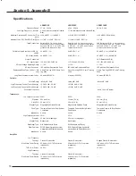
Page 18: ...V 5 amp Time Lag 250V 2 5 amp Time Lag 250V Long Term Maximum System Power 40 watts IEC265 5 21 watts IEC265 5 90 watts IEC265 5 Controls Volume Range infinity dB 0 dB infinity dB 0 dB infinity dB 0 d...

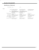
Page 19: ...0 in center to center M6 metric threads Enclosure Volume net 13 liter 0 46 cu ft 7 1 liter 0 25 cu ft 34 liter 1 2 cu ft Low Frequency Vent Rear ported integrated with amplifier heat sink Rear ported...

Page 20: ...ts Outside the USA Contact the JBL Professional Distributor in your area A complete list of JBL Professional international distributors is provided at our U S A website www jblpro com En Dehors des Et...

Page 21: ...e made if replacement cartons are requested Payment of shipping charges is discussed in the next section of this warranty How To Obtain Warranty Performance If your JBL product ever needs service writ...

Page 22: ...Part Number 365438 001 Rev 0709...

Reviews: