background image

Parameter

Specification

Unit

QA Test 

Limits

Conditions

Notes

Transients/Pops

ATO Transient

0.5

V-peak

0.5V

@ Speaker Output

Amplifier activated by signal presence at the 
Line input

Turn-on Transient

0.5

V-peak

0.8V

@ Speaker Output

AC Line cycled from OFF to ON

Turn-off Transient

0.5

V-peak

0.8V

@ Speaker Output

AC Line cycled from ON to OFF

Efficiency

Efficiency

61

%

60

Test conducted at rated power 
250W

Nominal Line voltage 

Efficiency at 1/8 of rated power

45

%

42

Test conducted at 31.25 WRMS

Nominal Line voltage-Rated impedance 4 
Ohms

Off state input power

12

Watts

14

Nominal Line voltage  RED LED

Stand-by Input Power

18

Watts

18

@ nom. line voltage

Maximum allowable  input power under 
nominal  Input voltage and frequency, HOT 
or COLD operation. LED GREEN no signal 
applied

Power Cons. @ rated power

367

Watts

375

@ nom. line voltage

225 Watts @ 4 Ohms nominal line voltage

Protections

Short Circuit Protection 

YES

functional  Direct short at output

Amplifier should resume operation after 
short circuit condition removal 

Thermal Protection 

YES

functional

@1/8 max unclipped Power at 
1.06 times the input voltage

Temperature rise in accessible metal parts 
should not exceed 35K rise for domestic 
version or 30K rise for European versions 
(refer to requirements sheet).

DC Offset Protection

YES

-

DC present at Speaker Out leads

Design must insure no Offset at the speaker 
output  under any operating condition 
including abnormal operation

Line Fuse Rating

USA-Domestic 3.15

Amps

3.15

Type-T or Slo Blo-250 V

Internal fuse with UL/SEMKO rated holder

EU

2

Amps

2

Type-T or Slo Blo-250 V, Low 
Breaking capacity

Internal fuse with UL/SEMKO rated holder

Other Parameters/Notes:

1. Limiter circuit response must be clean sounding with no apparent pops, noises, or pumping.
2. Plate dimensions not to exceed 11.81"H x 7.87"W and the plate must be airtight with no possibility of air leaks (plastic cover required).
3. Volume control should be 

at the input buffer stage

 in order to lessen the possibility of clipping the input section with highly dynamic audio material.

4. ALL SPECS SHOULD BE MEASURED AT NOMINAL LINE VOLTAGE. 


 ES150P 


3

Summary of Contents for ES150P

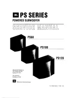
Page 1: ...ES Series ES150P Powered Subwoofer Service Manual JBL Consumer Products 250 Crossways Park Dr Woodbury New York 11797 Rev0 3 2008 Released 2008 Discontinued XXXX...

Page 2: ...equency Variable from 50Hz to 150Hz 24dB octave continuously variable Frequency Response 27Hz Low pass crossover setting Dimensions H x W x D 18 x 13 1 4 x 15 1 4 457mm x 337mm x 387mm Weight 39 lb 17...

Page 3: ...SNR unweighted 65 dBr 60 relative to 1W 22K filter Residual Noise Floor 2 0 mVrms max 2 5 Volume max w A P Swept Bandpass Measurement Line freq harmonics BW 20 KHz Line level inputs must be terminate...

Page 4: ...hould resume operation after short circuit condition removal Thermal Protection YES functional 1 8 max unclipped Power at 1 06 times the input voltage Temperature rise in accessible metal parts should...

Page 5: ...ES150P 4...

Page 6: ...4 Rear Panel CONTROLS AND CONNECTIONS AC 120V 60Hz 2A Phase Switch LFE Normal Selector Subwoofer Level Control Crossover Adjustment Line Level LFE Input Power Switch ES150P 5...

Page 7: ...ects LFE or subwoofer output 5 If your receiver processor does not contain a Dolby Digital or DTS processor but has subwoofer outputs Set line level LFE switch to Normal NOTE If your receiver processo...

Page 8: ...t the volume of the subwoofer so its impact on bass response is always there but never obtrusive Phase Control The Phase Switch determines whether the subwoofer speaker s pistonlike action moves in an...

Page 9: ...ES150P 8...

Page 10: ...l full clockwise MAX immediate and vigorous bass response should be heard and felt from port tube opening on the bottom 9 Turn off generator turn LEVEL control full counterclockwise MIN and disconnect...

Page 11: ...ES150P 10...

Page 12: ...ES150P 11...

Page 13: ...HD output power noise O Check pre board power board Vcc 15V etc Test frequency Response O Check U102 uR133 C121 R135 C122 etc Test input sensitivity O Check U101 R117 R112 R114 etc Test protection O C...

Page 14: ...ES150P 13...

Page 15: ...ES150P 14...

Page 16: ...ES150P 15...

Page 17: ...ES150P 16...

Page 18: ...ES150P 17...

Page 19: ...STOR 22 1K 1 6W 1 MF RoHS 6 R209 R231 R232 R296 R204 R206 116 162553F26 E METAL FILM RESISTOR 255K 1 6W 1 MF RoHS 1 R195 116 162611f26 e METAL FILM RESISTOR 1 6W 2 61K 1 RoHS 1 R253 116 162803f26 e ME...

Page 20: ...6 e METAL FILM RESISTOR 200K 1 4W 1 MF RoHS 1 R209 110 16102J26 E carbon resistor 1K 1 6W 5 CF RoHS 3 R210 R239 R264 110 16103J26 E carbon resistor 10K 1 6W 5 CF RoHS 9 R216 R227 R229 R230 R231 R232 R...

Page 21: ...R TSC05103J RoHS 1 R237 175 1c02v01 e WIRE CONNECTOR BASE 2PIN PITCH 2 5mm RoHS 1 P108 175 1c06v01 e WIRE CONNECTOR BASE 6 PIN PITCH 2 5mm RoHS 1 P107 175 1d02v01 e WIRE CONNECTOR BASE 2PIN PITCH 3 96...

Page 22: ...R BASE 2PIN PITCH 2 54mm RoHS 1 HDR3 175 9F03H020 E WIRE CONNECTOR BASE 3PIN PITCH 2 54mm RoHS 2 HDR1 HDR2 122 13151k0190 e CHOKE SA 500 280 PT1601B 151MAA RoHS 1 L1 122 14300k4 e Ferrite core LD1215...

Page 23: ...0 MACHINE SCREWCROSS BLK RoHS 4 352 AM03008D040 E 3 8 B TYPE PING SCREW CROSS BLK RoHS 2 352 AM03008D041 E 3 8 B TYPE PING SCREWCROSS WITH NICKEL RoHS 2 352 AM03010D065 E 3 10 P TYPE PING SCREWCROSS B...

Page 24: ...ES150P 23...

Page 25: ...ES150P 24...

Page 26: ...ES150P 25...

Page 27: ...ES150P 26...

Page 28: ...ES150P 27...

Page 29: ...ES150P 28...

Page 30: ...ES150P 29...

Page 31: ...ES150P 30...

Page 32: ...ES150P 31...

Page 33: ...ES150P 32...

Page 34: ...ES150P 33...

Reviews: