D. Wire Gauges and Line Loss Calculations
Good engineering practice requires that line losses result in no greater than a level loss of 0.5
at the load. In making the calculations to determine the smallest wire gauge that will ensure
adherence to this, the engineer must keep in mind that the loss at the loudspeaker is due to actual
losses in the wiring as well as to losses due to impedance mismatching caused by the added
resistance in the line. The following equation can be used to determine the loss in at the
loudspeaker, taking both factors into account:
Loss
= 20 log
+
where is the resistance in each of the two wire runs to the load and RL is the nominal load
impedance.
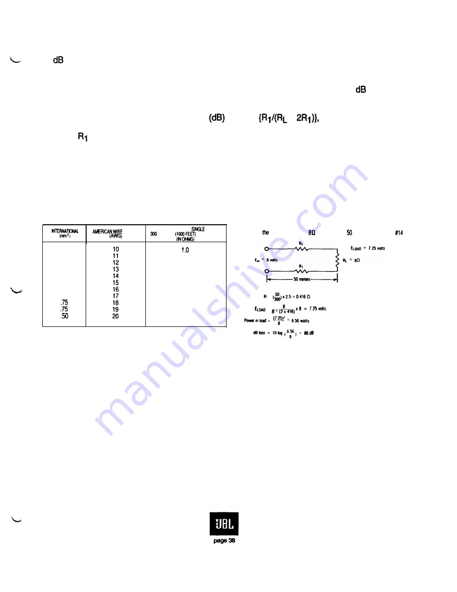
Details of the calculation method are shown in Figure 33. The simplest way to deal with wire
losses is by an iterative design process of selecting a trial gauge of wire, solving for the loss, and then
moving up or down in wire gauge as required to meet the design criterion.
GAUGE
RESISTANCE PER
RUN.
METERS
OF COPPER
6.00
6.00
2.50
2.50
1.50
1.50
1.00
1.00
1.2
1.6
2.0
2.5
3.2
4.0
5.0
6.3
8.0
10.0
NOTE.
Paralleling two identical AWG gauges reduces effective gauge by 3.
EXAMPLE:
Find power loss at an load due to a meter run of AWG wire.
=
=
Figure 33. Wire loss calculations
E. Dividing Network Characteristics
The
primary purpose of a passive dividing network is to feed various parts of the frequency
range into the intended transducers. In addition, practical networks provide for some degree of level
adjustment (usually for the high frequency section only) so that elements of various sensitivities can
be used together. Recent network designs provide additional high frequency power response
equalization, and a very few passive networks provide some degree of time offset (normally in the low
frequency section) to enable specific high and low frequency elements to combine response properly
at the crossover frequency. Active networks accomplish their various operations electronically and are
used in biamplification.


