background image

4-2

Maxor User’s Manual

www.javad.com

4

O P E R A T I O N

Using MinPad

Using MinPad

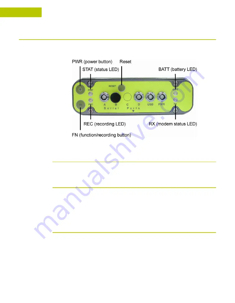
The MinPad is Javad's minimum interface used to display and control data input 
and output (Figure 4-1).

Figure 4-1. Maxor MinPad

Power Key

Pressing the 

power

 key turns the receiver on and off.

Status LED

• When the receiver is on and no satellites are tracked, the STAT LED will 

blink red.

• When satellites are tracked, the STAT LED will produce one blink for each 

tracked satellite (green for GPS, orange for GLONASS).

Reset Key

Pressing the reset key for about one second causes:

• a hard reset of the receiver.

• the receiver to leave Zero Power Mode and return to Normal Mode.

Summary of Contents for Maxor

Page 1: ...Maxor GNSS Receiver User s Manual Copyright Javad Navigation Systems Inc March 2004...

Page 2: ......

Page 3: ...ling Requirements XXI Manual Conventions XXI Chapter 1 Introduction 1 1 Overview 1 2 Principles of Operation 1 3 GPS Overview 1 3 Calculating Positions 1 4 GPS Positioning 1 4 Conclusion 1 5 Receiver...

Page 4: ...tery Charger 2 3 Power Management 2 4 Charging the Maxor 2 7 Connecting the Maxor and a Computer 2 8 Establishing a Wireless Connection 2 8 Establishing an RS 232 Cable Connection 2 9 Establishing a U...

Page 5: ...se Station 3 12 Setting up an RTK Rover 3 15 Chapter 4 Operation 4 1 Using MinPad 4 2 Power Key 4 2 Status LED 4 2 Reset Key 4 2 FN Key and Record LED 4 3 Battery LED 4 5 Modem LED 4 6 Information Mod...

Page 6: ...luetooth Problems 5 7 Obtaining Technical Support 5 10 E mail 5 10 Website 5 10 Appendix A A 1 Creating Scripts A 1 Appendix B B 1 Specifications B 1 Maxor Specifications B 1 Connector Specifications...

Page 7: ...www javad com Maxor User s Manual V TA BL E OF CONTENTS Internal Battery Pack Warnings C 2 Usage Warnings C 2 Appendix D D 1 UHF Radio Usage D 1 Appendix E E 1 Warranty Terms E 1 Index...

Page 8: ...VI Maxor User s Manual www javad com Notes...

Page 9: ...r Charging 2 4 Select Power Mode 2 5 Select Charger Mode 2 5 Select Power Output Modes Ports 2 6 Select Power Output Modes Slots 2 6 View Voltages Information 2 6 Enable Slots 2 7 Activate Low Power M...

Page 10: ...Capture Method Soft Break 2 24 Click Load 2 24 PDL Identification Tab 2 25 PDL Radio Link Tab 2 26 PDL Serial Interface Tab 2 27 PDL Click Program 2 27 Click Close then Exit 2 28 Connection Parameter...

Page 11: ...ion 3 16 Rover Configuration Ports 3 17 Chapter 4 Operation 4 1 Maxor MinPad 4 2 Connection Parameters RTS CTS Handshaking 4 8 File File MAnager 4 8 Find Files to Download 4 9 Download Files 4 9 Downl...

Page 12: ...X Maxor User s Manual www javad com LIST OF FIGURES RS 232C Connector B 10 USB Connector B 11...

Page 13: ...ating Times 2 2 Data Recording Parameter Behavior 2 20 Parameters for Selected Link Rate 2 25 Chapter 3 Setup and Survey 3 1 Antenna Offset Values 3 3 Antenna Offset Measurements 3 5 Chapter 4 Operati...

Page 14: ...B 1 Receiver Specifications B 1 Pacific Crest PDL UHF Modem Connector Specifications B 9 Spread Spectrum GSM Modem Connector Specifications B 9 Power Connector Specifications B 10 RS 232C Connector S...

Page 15: ...sive to TPS which are the fields of surveying construction commercial mapping civil engineering precision agriculture land based construction and machine control photogrammetry mapping and hydrographi...

Page 16: ...ANUAL AND THE MAXOR ARE PROVIDED AS IS THERE ARE NO OTHER WARRANTIES JNS DISCLAIMS ANY IMPLIED WARRANTY OF MERCHANTABILITY OR FITNESS FOR ANY PARTICULAR USE OR PURPOSE JNS AND ITS DISTRIBUTORS SHALL N...

Page 17: ...confidential and proprietary information of JNS You agree to treat JNS Confidential Information with a degree of care no less stringent that the degree of care you would use in safeguarding your own m...

Page 18: ...with the limits for a Class B digital device pursuant to Part 15 of the FCC rules These limits are designed to provide reasonable protection against harmful interference in residential installations T...

Page 19: ...anual Conventions This manual uses the following conventions Tip Supplementary information that can help you configure maintain or set up a system Notice Supplementary information that can have an aff...

Page 20: ...XVIII Maxor User s Manual www javad com Notes...

Page 21: ...lements Also a brief description of the principals of GPS operation is presented This information is split into the following sections Overview page 1 2 Principles of Operation page 1 3 Receiver Overv...

Page 22: ...satellites of the United States and the GLONASS Global Navigation Satellite System satellites of the Russian Federation increasing the number of satellites your receiver can detect thus improving the...

Page 23: ...15 degree angle up to 10 or 12 GPS satellites are visible from any point on earth When a receiver can also track GLONASS satellites between 10 and 16 satellites are visible For information on the cur...

Page 24: ...ephemeris data cyclically with a period of 30 seconds GPS satellites broadcast almanac data cyclically with a period of 12 5 minutes GLONASS satellites broadcast almanac data cyclically with a period...

Page 25: ...ignals for processing An internal antenna equipped with a low noise amplifier LNA and the receiver s radio frequency RF device are connected with a coaxial cable The wide band signal received is down...

Page 26: ...ent accessories available please contact your local Javad dealer or visit the accessoriessectionoftheJNSwebsite http www javad com cgi bin WebShop cgi Action DrawAccessoriesList Unpack the kit content...

Page 27: ...e applications FLoader Javad s firmware loader available on the JNS website PDLCONF from Pacific Crest firmware upgrades available from the Pacific Crest website www paccrst com download upgrade htm B...

Page 28: ...GLONASS L1 L2 signals Bluetooth Module A combination of software and hardware technology that makes the Maxor mobile wireless GNSS receiver that supports a point to point serial profile As such the M...

Page 29: ...er of preset frequencies programmed at JNS WARNING The use of these preset frequencies without a license is illegal Contact your local authorities the FCC in the US to use these preset frequencies Onc...

Page 30: ...ith a full charge the internal batteries should power both the GNSS receiver and the UHF radio modem for at least 15 working hours for the Maxor GD GG or 12 working hours for the Maxor GGD If the inte...

Page 31: ...interface a power port and ports for configuration Radome Figure 1 2 shows the radome components Internal antenna Location of GPS GLONASS internal antenna Modem antenna connector Modem antenna connect...

Page 32: ...Panel Figure 1 3 shows the Maxor s bottom panel components Antenna Reference Point ARP The GPS GLONASS external antenna connector standard configuration Figure 1 3 Maxor Bottom Panel Front Panel Figur...

Page 33: ...ualizes the pressure between the inside of the receiver and the outside environment USB Only available on the Maxor GGD with the Euro 112 card Used for high speed data transfer and communication betwe...

Page 34: ...eded Typically all Maxor receivers ship with a temporary OAF that allows the receiver to be used for a predetermined period of time When the receiver is purchased a new OAF activates desired purchased...

Page 35: ...rging the Maxor page 2 7 Connecting the Maxor and a Computer page 2 8 Maxor Configuration page 2 12 MinPad Configuration page 2 15 Radio Configuration page 2 21 Bluetooth Module Configuration page 2 3...

Page 36: ...external power source allows you to continue using the receiver in case the internal batteries are discharged The appropriate external power source must provide 6 to 28 V DC and must be able to suppl...

Page 37: ...sed to charge the internal batteries can be used as an external power supply for the receiver The charger is provided with the standard receiver package To use power from the battery charger connect t...

Page 38: ...akes power from the external source Solid light an External power supply is used and the batteries are not being charged Blinking once a second an external power supply is used and the batteries are b...

Page 39: ...displays the current power source Figure 2 2 Select Power Mode Auto receiver automatically selects the power source Mix receiver automatically detects and consumes power from the source with the large...

Page 40: ...connectors even if the receiver is off 6 Select the Power output modes Slots drop down list to set power output on internal slots Figure 2 5 Figure 2 5 Select Power Output Modes Slots On all slots ha...

Page 41: ...08016 03 into the power port of the receiver labeled PWR Connect the opposite end of this cable with the battery charger s SAE connector Plug the appropriate end of the power supply to outlet cable in...

Page 42: ...driver for such connection Once you have established a connection between the receiver and the computer you will be able to Configure the receiver and its components Send commands to the receiver Dow...

Page 43: ...blishing a PCView Connection on page 2 10 If you cannot establish a connection check that the receiver s slot three is enabled 1 Connect your receiver and a computer using an RS232 cable see Establish...

Page 44: ...available on the JNS website 1 Once the receiver and a computer are connected start PCView on your computer The PCView main screen displays Figure 2 9 Figure 2 9 PCView Main Window Notice that the lo...

Page 45: ...rs For USB connections Figure 2 11 Set the Connection mode Direct Set the port for your computer USB from the Port drop down list Select the receiver s ID from the Rec ID drop down list Figure 2 11 US...

Page 46: ...full range of PCView configuration and function is outside the scope of this manual Notice Refer to the PCVIEW User s Manual to manage all possible Maxor receiver configurations The following configu...

Page 47: ...the Recording interval in seconds Set the Elevation mask for Log file in degrees Enter the File name prefix Use the last three digits of the receiver serial number The receiver s serial number is on t...

Page 48: ...Apply Figure 2 16 Code multipath reduction Carrier multipath reduction Figure 2 16 Advanced Configuration Multipath Reduction 3 Click the Loop Management tab enable the following boxes and click Appl...

Page 49: ...ring the NVRAM MinPad Configuration The Maxor s minimum interface MinPad consists of three keys Power FN and Reset and up to four LEDs STAT REC BATT and RX that control and display the receiver s oper...

Page 50: ...View User s Manual for all possible MinPad configurations 1 Connect your receiver and computer See Connecting the Maxor and a Computer for this procedure 2 On the Connection Parameters dialog box enab...

Page 51: ...key pressed for 1 5 seconds activates data logging This setting is used not only when logging a single log file but also when logging receiver data in AFRM mode Values are 1 86400 seconds The default...

Page 52: ...e Rotation Mode AFRM parameters JNS receivers are capable of automatically rotating log files During a file rotation event the receiver closes the current file and opens a new one according to a user...

Page 53: ...s FIFO First In First Out feature The default value is off disabled FN Key Mode parameter You use these two radio buttons to program how the receiver will react when pressing the FN key LED blink mode...

Page 54: ...ults Off On Always 1 Receiver data logged to file specified Data logging will not resume when power is restored Receiver will resume data logging to the same file when power is restored Receiver will...

Page 55: ...UHF and GSM radio modems Notice Your receiver may be configured without a radio modem If this is the case please skip to Bluetooth Module Configuration on page 2 31 Configuring a UHF Radio Modem To ac...

Page 56: ...f QUIT set cur term echo dev null set cur term imode echo set cur term echo dev ser c The Manual Mode screen will show RE002 in response to each of these commands When finished you should see a window...

Page 57: ...tware are available on the Pacific Crest website www paccrst com download upgrade htm Figure 2 24 PDL Radio Configuration Main Screen 7 Click the Pacific Crest logo in the upper left corner of the mai...

Page 58: ...Figure 2 27 Figure 2 27 Select Serial Port and click OK Notice If in doubt about the location of your modem click Locate Modem In this way PDLCONF will try to automatically capture your modem This pro...

Page 59: ...t the following parameters depending on the link rate selected Table 2 3 and Figure 2 31 Table 2 3 Parameters for Selected Link Rate Controls Link Rate 9600 19200 Channel Select Manual Channel TX RX e...

Page 60: ...be configured with the same Channels Radio Link characteristics except Digisquelch and Serial Interface parameters Typically Digisquelch is set on High for Rover and Low for Base station 14 Click the...

Page 61: ...GU R AT I O N Radio Configuration BREAK to Command disable Figure 2 32 PDL Serial Interface Tab 15 If you made changes click the Program button on the left of the screen to save them to the modem s me...

Page 62: ...ction Parameters screen select a baud rate of 38400 and enable the Manual mode only check box Figure 2 35 then click Connect Figure 2 35 Connection Parameters Manual Mode Only 20 On the Manual Mode sc...

Page 63: ...the user and the GSM radio modem To access your GSM radio modem you will need to use FieldView or PCView FieldView users can configure the GSM radio modem through the program s GUI whereas PCView use...

Page 64: ...r modem c pin wxyz where wxyz stands for a specific four digit PIN e g set par modem c pin 6492 Command 3 Notice Mandatory only when running the GSM modem in master mode Enter the dial number i e the...

Page 65: ...computer to access the Bluetooth wireless technology module configure the Bluetooth module check or change the module s configuration To access the Bluetooth wireless technology module first download...

Page 66: ...tion click the About button 4 From the drop down list in the upper left corner select the computer serial port used for communication Figure 2 39 Figure 2 39 Select Communication Port and Click Connec...

Page 67: ...dule 7 Enter up to 14 characters to set a unique name for the Bluetooth module Figure 2 41 and click Apply Figure 2 41 BTCONF Parameters Tab 8 To set security parameters Figure 2 42 enter and enable t...

Page 68: ...ure 2 43 BTCONF Serial Interface Tab 10 Click Disconnect then Exit to quit BTCONF Collecting Almanacs Each satellite broadcasts a message almanac which gives the approximate orbit for itself and all o...

Page 69: ...ay need to clear the NVRAM See Clearing the NVRAM on page 4 14 for this procedure You will need to collect or update the almanac If the receiver has been off for a long time If the last known receiver...

Page 70: ...2 36 Maxor User s Manual www javad com Notes...

Page 71: ...iguration 2 Set up your Base or Rover station See Step 1 on page 3 2 3 Measure the antenna height See Step 2 on page 3 2 for internal antennas or see External Antenna Setup on page 3 4 for external an...

Page 72: ...n larger in area than can reliably fit on a flat plane therefore the antenna adjustment must be done in three dimensions and then projected onto a two dimensional plane The receiver calculates the coo...

Page 73: ...being at a physical surface of the prism In the case of a GPS GLONASS antenna the offset is entered depending on the type of measurement taken For vertical the offset is simply added to the measured...

Page 74: ...ne second and less than five seconds 2 Release the FN key when the REC recording LED light turns green This indicates that a file has opened and data collection has started The REC LED blinks each tim...

Page 75: ...arAnt Antenna Offset Measurements 3 Record the antenna height point name and start time in the field notes 4 Attach the flexible RF cable from the external antenna to the antenna connector on the bott...

Page 76: ...oes not detect the external antenna use the procedure below to set the External Antenna detection option 1 Connect your receiver and computer See Connecting the Maxor and a Computer on page 2 8 for th...

Page 77: ...servation session length depends on the surveyor s experience as well as the following factors The length of the baseline measured The number of satellites in view The satellite geometry DOP The anten...

Page 78: ...ecting the Maxor and a Computer on page 2 8 for this procedure 2 Open PCView click Configuration Receiver MinPad and specify the following parameters then click Apply Figure 3 5 Recording Interval 15...

Page 79: ...ath 1 Click the Loop Management tab and set the following parameters then click Apply Figure 3 7 Enable Common Tracking enable Static mode enable disable for Rover receivers Figure 3 7 Advanced loop M...

Page 80: ...ing PCView configure and set up the Base as described in Static Survey on page 3 7 2 Using PCView click Configuration Receiver MinPad and configure the Rover with the following parameters then click A...

Page 81: ...as trajectory surveying allows the Rover to move without having to stand still record data move to another point and repeat the procedure If the surveyor knows the coordinates of the starting point t...

Page 82: ...TK is a differential GPS process where information such as differential corrections is transmitted in real time from a Base station to one or more Rover stations Setting up an RTK Base Station To conf...

Page 83: ...creen select the MinPad tab Specify desired settings Refer to the PCView User s Manual for more information 9 Select the Positioning tab and set the Position Masks Elevation mask parameter to 15 Figur...

Page 84: ...inates are zeros Notice The reference geodetic coordinates you specify on this tab relate to the antenna L1 phase center Figure 3 11 Base Tab Configuration 11 Select the Ports tab and set the followin...

Page 85: ...lect the radio transmission power using the Low High toggle on the rear panel of the modem When in High the AMP PWR LED will be on 15 Use the Channel button to set the frequency channel Check that the...

Page 86: ...ion RTK applications The Rover RTK engine will compute either a delayed RTK position for the epoch to which the newly received RTCM CMR message corresponds or the current stand alone position while wa...

Page 87: ...d in WGS84 and have four solution types Standalone where receiver computes 3D coordinates in autonomous mode without using differential corrections Code differential where the Rover receiver computes...

Page 88: ...e Maxor Total number of received corrupt messages If the receiver is not for some reason receiving differential corrections or if none of the ports has been configured to receive differential correcti...

Page 89: ...cedures Using the MinPad page 4 2 Downloading Files to a Computer page 4 7 Deleting Files page 4 10 Checking an OAF page 4 11 Loading an OAF page 4 13 Managing Receiver Memory page 4 13 Clearing the N...

Page 90: ...ng the power key turns the receiver on and off Status LED When the receiver is on and no satellites are tracked the STAT LED will blink red When satellites are tracked the STAT LED will produce one bl...

Page 91: ...Authorization File OAF on page 1 14 for more information on OAFs The REC LED blinks green or orange each time data is written to the internal receiver s memory You set the data recording time interval...

Page 92: ...No free memory hardware problem with data recording Pressed for 1 second If FN key mode is LED blink mode switch Orange Release to charge information mode If FN key mode is Occupation mode switch Oran...

Page 93: ...efined If FN key mode is Occupation mode switch Green Data recording started Kinematic post processing occupation mode Orange Data recording started Static post processing occupation mode Pressed for...

Page 94: ...ternal power is connected the receiver will go into Zero Power Mode to prevent the batteries from over discharging Modem LED The color of the RX LED indicates if the modem has power is receiving signa...

Page 95: ...time is more than 15 minutes In EIM the STAT LED blinks seven times per cycle Each blink could be orange red or green Orange information for test unavailable Green receiver passed the test Red receive...

Page 96: ...collecting data at the jobsite PCView provides a File Manager to download files to your computer and delete files from the Maxor 1 Connect your receiver and computer See Connecting the Maxor and a Com...

Page 97: ...to download and store files Open this new folder 6 Select the Download files tab 7 Select the file s you want to download Figure 4 5 To select multiple files hold down the shift key and click on nons...

Page 98: ...delete files from your receiver 1 Connect your receiver and computer See Connecting the Maxor and a Computer on page 2 8 for this procedure 2 On the Connection Parameters dialog box enable RTS CTS han...

Page 99: ...ile Exit to quit PCView Checking an OAF Tip For a complete list of options and their details visit the JNS website You can check the status of your receiver s options and load any new OAFs using the R...

Page 100: ...date the date the option will be disabled if applicable Since Options can be both purchased and leased the Current status of the option displays the currently effective value Option values can be 1 or...

Page 101: ...ure 4 10 Figure 4 10 Load OAF 4 Select the appropriate file and click Open Figure 4 10 The new receiver option loads onto the receiver and the Option Manager table updates 5 When finished click Exit o...

Page 102: ...a soft boot in your computer After clearing the NVRAM your receiver will require some time to collect new ephemerides and almanacs around 15 minutes Clearing the NVRAM of your receiver will not delet...

Page 103: ...dly flashes green and red the STAT LED flashes red Figure 4 11 Tools Clear NVRAM The receiver will automatically disconnect once the NVRAM is cleared Changing Receiver Modes The Maxor receiver has fou...

Page 104: ...n less than two months To stop the power board from draining the batteries you can put your receiver in Zero Power Mode 1 Turn on your receiver 2 Press and hold the power key for more than 8 seconds b...

Page 105: ...iver model Receiver IDs Firmware version 3 When finished click OK then click File Disconnect to prevent conflicts with serial port management Loading New Firmware Base and Rover receivers must be load...

Page 106: ...the FLoader User s Manual also available on the JNS website 1 Download and install FLoader if applicable 2 Download the new firmware package to your computer 3 Physically connect your receiver and com...

Page 107: ...eiver board s RAM file and Flash file Figure 4 16 10 Click Load and wait until 100 of the files load into your receiver Notice If you selected an incorrect RAM or Flash file an error message displays...

Page 108: ...elect the Power board s RAM file Figure 4 18 15 Click Load and wait until 100 of the power board file loads into your receiver Notice If you selected an incorrect RAM file an error message displays at...

Page 109: ...is chapter will help you diagnose and solve some common minor problems you may encounter with your Maxor receiver This chapter provides the following sections Things to Check First page 5 2 Power Prob...

Page 110: ...rs to defaults Clear the NVRAM see Clearing the NVRAM on page 4 14 Initialize the file system click Tools Initialize file system this will erase all files inside the receiver WARNING Do not attempt to...

Page 111: ...Powering the Maxor on page 2 2 The receiver may have a defective charger or defective internal batteries If after charging your internal batteries overnight and your Maxor is not powering contact JNS...

Page 112: ...not lock on to satellites for a long period of time Causes Solutions The receiver stores an old almanac Update the almanac See Collecting Almanacs on page 2 34 The antenna cable is damaged Use an unda...

Page 113: ...esponding receiver options by ordering a new OAF with the desired options activated There are not enough common satellites In order to obtain a fixed solution the Base and Rover should track at least...

Page 114: ...rmation See Radio Configuration on page 2 21 for checking the current link rate and changing the link rate The specified baud rate is not compatible with the baud rates the modem supports The baud rat...

Page 115: ...ble s connectors are improperly attached Check that the cable connector is attached to the correct serial port Unplug the cable then securely and properly reconnect it to the receiver If using a cable...

Page 116: ...ssage Can t find Bluetooth Causes Solutions The receiver s Slot 3 is turned off 1 Connect your receiver and a computer using an RS232 cable see Connecting the Maxor and a Computer on page 2 8 2 Click...

Page 117: ...new cable The receiver s Slot 3 is turned off 1 Connect your receiver and a computer using an RS232 cable see Connecting the Maxor and a Computer on page 2 8 2 Click Configuration Receiver General 3...

Page 118: ...r your particular question please send it to support javad com Website The Javad Positioning Systems website provides current information about Javad s line of products The support area of the website...

Page 119: ...ormation on script files see the PCView User s Manual 1 Connect your receiver and computer See Connecting the Maxor and a Computer on page 2 8 for this procedure 2 Start PCView 3 Click on File Manual...

Page 120: ...e dialog box 2 Navigate to the folder that contains your script file 3 Select the appropriate script file and click Send command Table A 1 Script Commands To Create Daisy Chain To End Daisy Chain set...

Page 121: ...and a rugged aluminum housing complete with MinPad and cable connectors Maxor Specifications Table B 1 lists receiver component details Table B 1 Receiver Specifications Component Details Receiver Ty...

Page 122: ...and Carrier WAAS EGNOS Survey Mode Static Kinematic Continuous Stop and Go RTK Real time Kinematic DGPS Differential GPS Survey Accuracy Static Fast Static For L1 L2 H 3mm 1ppm x D V 5mm 1 4ppm x D F...

Page 123: ...iscellaneous Supported profiles LM L2CAP SDP PPP Frequency Country Code North America and Europe Data Storage and Display Status Indicators Four three color LED s Controls Three function keys Data Fea...

Page 124: ...GPS GLONASS Antenna Internal Antenna Type Microstrip Memory Internal Memory Compact flash card not removable Capacity Standard 0 MB Max 512 MB Maxor GD or 1 GB Maxor GGD Logging Time 53 hours 8 MB 15...

Page 125: ...rrent 2 Amp Consumption Typical 2 5W Maximum 2 7W On board Backup battery for timekeeping and almanac data storage 10 years minimum operation Environment Operating temperature 30 C to 60 C with batter...

Page 126: ...RMC VTG ZDA ROT Output interval 1Hz standard 5 10 20Hz optional DGPS Correction format RTCM SC104 Ver 2 1 2 2 and 2 3 RTCM message type 1 3 9 31 32 34 user selectable Process interval 1Hz standard 5...

Page 127: ...nal Latency Delay mode 20 msec to 20 sec depends on latency which receives corrections data from base receiver Extrapolation 20 to 30 msec Raw Data Logging The receiver can record raw data at another...

Page 128: ...individual PLL Bandwidth of common PLL Smoothing interval Code and Carrier WAAS EGNOS Standard Battery Charger AC Adapter Size W 63 5 x L 102 x H 32 5 mm Weight 400 g Operating Temperature 0 C to 33...

Page 129: ...PDOP and during periods of increased ionospheric activity performance may degrade Notice Use robust checking procedures in areas of extreme multipath or under dense foliage Connector Specifications T...

Page 130: ...wer connector specifications Serial RS 232C Connector For ports A and D The RS232 connectors Figure B 2 are sealed receptacle 7 pin ODU p n G80F1C T07QC00 0000 Figure B 2 RS 232C Connector Table B 4 P...

Page 131: ...ure B 3 USB Connector Table B 6 gives the USB connector specifications Table B 5 RS 232C Connector Specifications Number Signal Name Dir Details 1 Power_OUT P Power Output supplied voltage 2 GND Signa...

Page 132: ...T and 1PPS Connectors Optional The EVENT and 1PPS connectors are coaxial female receptacles of BNC series Kings Electronics part number KC 79 108 These connectors are optional 4 USB D I O Data plus 5...

Page 133: ...veying coordinates distances angles and depths and recording such measurements This product should never be used Without the user thoroughly understanding this manual After disabling safety systems or...

Page 134: ...receiver s warranty Do not attempt to open the battery pack or replace it Do not disassemble the battery pack Do not charge in conditions different than specified Do not use other than the specified b...

Page 135: ...s The following concepts will help you get the most out of your UHF based communication systems 1 Your system s range will greatly depend on the local conditions Topography local communications and ev...

Page 136: ...tional antennas and or repeaters to increase your system s range Directional antennas concentrate the signal power within a more narrow direction significantly increasing the range of your system Chec...

Page 137: ...e to repair damage to the product resulting from an accident disaster misuses abuse or modification of the product Warranty service may be obtained from an authorized JNS warranty service dealer If th...

Page 138: ...E 2 Maxor User s Manual www javad com Notes...

Page 139: ...oth 1 8 2 8 2 10 2 31 BTCONF install 2 31 uninstall 2 31 C Cables 1 6 extension 1 6 part numbers 1 6 receiver to SAE 1 6 RS 232C 1 6 USB 1 6 Charge internal batteries 2 7 Checking Firmware Version 4 1...

Page 140: ...ntenna 1 8 offsets 3 3 Internal batteries 1 10 2 2 charge 2 7 status 2 7 Internal components 1 8 Internal radio 1 8 configuration 2 21 K Kinematic Continuous configuration 3 11 Kinematic survey 3 10 L...

Page 141: ...ers 2 9 RTK 1 2 RX LED 4 6 S Scripts 2 22 create A 1 Security parameters 2 33 SHMM 1 13 Sleep mode 4 15 Software BTCONF 1 7 Ensemble 1 7 FieldView 1 7 FLoader 1 7 4 18 PCView 1 7 PDLCONF 1 7 Start sto...

Page 142: ...Index Maxor User s Manual www javad com Notes...

Reviews: