background image

2-6


LGG100 Operator’s Manual

www.javad.com

S E T U P   A N D   M E A S U R I N G

DGPS Measuring with the LGG100

2

Figure 2-4. Receiver Configuration – Positioning

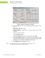
10. Select the 

Base

 tab and set the following parameters (Figure 2-5 on 

page 2-7):

GPS/GLO at one time

 - enable

Antenna position

 - enter Lat, Lon, and Alt values. Do one of the 

following:

–If known, type in the values.

–Click 

Get from receiver

.

–Enable 

Averaged

 and enter the in seconds, then click 

Apply

11. Click 

Tools->Reset receiver

 and wait until the specified interval (span) 

completes. Examine the Base coordinates on the Base tab; they should 
correspond to the coordinates obtained from the average. 

12. Click 

Refresh

 if the coordinates are zeros.

Notice:

The reference geodetic coordinates you specify on this 
tab relate to the antenna L1 phase center.

Summary of Contents for LGG100

Page 1: ...ugust 2006 All contents in this manual are copyrighted by JNS All rights reserved The information contained herein may not be used accessed copied stored displayed sold modified published or distributed or otherwise reproduced without express written consent from JNS ...

Page 2: ......

Page 3: ...iance x FCC Class B Compliance x Canadian Emissions Labeling Requirements xi Screen Captures xi Manual Conventions xi Chapter 1 Introduction 1 1 Overview 1 2 Principles of Operation 1 3 GPS Overview 1 3 Calculating Positions 1 4 GPS Positioning 1 4 Conclusion 1 5 Receiver Overview 1 5 LGG100 Accessory Kit 1 6 Cables 1 6 Software 1 7 Literature 1 7 ...

Page 4: ... Connecting the LGG100 and a Computer 2 2 Establishing an RS232 Cable Connection 2 2 Establishing a PCView Connection 2 2 LGG100 Receiver Setup 2 4 DGPS Measuring with the LGG100 2 5 Setting up an DGPS Base Station 2 5 Setting up an DGPS Rover 2 9 Chapter 3 Operation 3 1 Checking an OAF 3 2 Loading OAFs 3 3 Clearing the NVRAM 3 4 Using PCView to Clear NVRAM 3 5 Checking Firmware Version 3 5 Loadin...

Page 5: ... 7 Appendix A A 1 Creating Scripts A 1 Appendix B B 1 Specifications B 1 General Details B 1 GPS Board Details B 3 Connector Specifications B 4 Power Connector B 4 Serial RS 232C Connector B 5 GPS External Antenna RF Connector B 5 Appendix C C 1 Safety Warnings C 1 General Warnings C 1 Usage Warnings C 2 Appendix D D 1 Warranty Terms D 1 ...

Page 6: ...iv LGG100 Operator s Manual www javad com Notes ...

Page 7: ...eiver Configuration Positioning 2 6 Base Tab Configuration 2 7 Base Configuration Ports 2 7 Port output setup 2 8 Rover Tab Configuration 2 9 Rover Configuration Ports 2 10 Tools Receiver Options 3 2 Option Manager 3 3 Load OAF 3 4 Tools Clear NVRAM 3 5 Help About 3 5 About PCView 3 6 Floader Main Screen 3 7 Set Device Type 3 7 Program Tab Settings 3 8 Power Connector B 4 RS 232C Connector B 5 ...

Page 8: ...vi LGG100 Operator s Manual www javad com Notes ...

Page 9: ...nstructions before operating inspecting or adjusting Always wear the required protectors safety shoes helmet etc when operating the receiver COPYRIGHT All information contained in this Manual is the intellectual property of and copyrighted material of JNS All rights are reserved You may not use access copy store display create derivative works of sell modify publish distribute or allow any third p...

Page 10: ... ADDITION JNS IS NOT RESPONSIBLE OR LIABLE FOR DAMAGES OR COSTS INCURRED IN CONNECTION WITH OBTAINING SUBSTITUTE PRODUCTS OR SOFTWARE CLAIMS BY OTHERS INCONVENIENCE OR ANY OTHER COSTS IN ANY EVENT JNS SHALL HAVE NO LIABILITY FOR DAMAGES OR OTHERWISE TO YOU OR ANY OTHER PERSON OR ENTITY IN EXCESS OF THE PURCHASE PRICE FOR THE LGG100 LICENSE AGREEMENT Use of any computer programs or software supplie...

Page 11: ...al In the event you become legally compelled to disclose any of the Confidential Information you shall give JNS immediate notice so that it may seek a protective order or other appropriate remedy WEBSITE OTHER STATEMENTS No statement contained at the JNS website or any other website or in any other advertisements or JNS literature or made by an employee or independent contractor of JNS modifies th...

Page 12: ...ay cause undesired operation This equipment has been tested and found to comply with the limits for a Class B digital device pursuant to Part 15 of the FCC rules These limits are designed to provide reasonable protection against harmful interference in residential installations This equipment generates uses and can radiate radio frequency energy and if not installed and used in accordance with the...

Page 13: ...e toutes les exigences du Réglement sur le matériel brouilleur du Canada Screen Captures This manual includes sample screen captures Your actual screen can look slightly different from the sample screen due to the receiver you have connected operating system used and settings you have specified This is normal and not a cause for concern Manual Conventions This manual uses the following conventions...

Page 14: ...hat an action has the potential to adversely affect system operation system performance data integrity or personal health WARNING Notification that an action will result in system damage loss of data loss of warranty or personal injury DANGER UNDER NO CIRCUMSTANCES SHOULD THIS ACTION BE PERFORMED ...

Page 15: ...s features and physical elements In addition a brief description of the principals of GPS operation is presented This information is split into the following sections Overview 1 2 Principles of Operation 1 3 Receiver Overview 1 5 LGG100 Accessory Kit 1 6 Getting to Know Your LGG100 1 7 Option Authorization File OAF 1 9 ...

Page 16: ... 1 1 LGG100 Receiver The LGG100 can receive and process L1 signal The GNSS component of LGG100 receivers means you can access both the GPS Global Positioning System satellites of the United States and the GLONASS Global Navigation Satellite System satellites of the Russian Federation increasing the number of satellites your receiver can detect thus improving the accuracy of your measuring points i...

Page 17: ...andard 15 degree angle up to 10 or 12 GPS satellites are visible from any point on earth When a receiver can also track GLONASS satellites between 10 and 16 satellites are visible For information on the current status of the GPS constellation visit http tycho usno navy mil or http www navcen uscg gov For GLONASS visit http www glonass center ru frame html Despite numerous technical differences in ...

Page 18: ...nly GLONASS the receiver must lock onto a fifth satellite Six satellites will provide fault tolerance in mixed scenarios Usually the number of GPS and GLONASS satellites in view does not exceed twenty 20 Once locked on to a satellite the receiver collects ephemerides and almanacs saving this information to its NVRAM Non Volatile RAM GPS and GLONASS satellites broadcast ephemeris data cyclically wi...

Page 19: ...lay Service EGNOS creates and transmits DGPS correction messages Five or more visible satellites for only GPS or only GLONASS six or more satellites for mixed scenarios Current ephemerides and almanacs Several algorithms to detect and correct faulty information Conclusion GNSS users can use JNS GNSS receivers to collect data from a network of satellites and control stations to triangulate precise ...

Page 20: ...sed using a post processing software package Depending on your options capabilities of the receiver include Multipath reduction Wide Area Augmentation System WAAS and European Geostationary Navigation Overlay Service EGNOS Differential GPS DGPS measuring modes Setting different mask angles Setting different measuring parameters LGG100 Accessory Kit Unpack the kit contents and check all the items t...

Page 21: ...e JNS website Literature LGG100 literature including manuals and other product information are available on the JNS website http www javad com LGG100 Operator s Manual Functional specifications The following manuals will also be useful for operating and caring for your LGG100 receiver PCView Software Manual FLoader User s Manual Getting to Know Your LGG100 The LGG100 is 150 mm wide 35 mm deep and ...

Page 22: ...nd almost unlimited altitude and velocity for authorized users have been industry proven in Aerospace applications such as numerous successful sounding rocket launches External Components The LGG100 casing includes panel for antenna attachment a power port and two ports for configuration Front Panel Figure 1 2 shows the LGG100 s front panel components LED PWR A B ANT Figure 1 2 LGG100 Front Panel ...

Page 23: ... those options needed Typically all LGG100 receivers ship with a temporary OAF that allows the receiver to be used for a predetermined period When the receiver is purchased a new OAF activates desired purchased options permanently Receiver options remain intact when clearing the NVRAM or resetting the receiver The OAF enables the following kinds of functions for LGG100 For a complete list of avail...

Page 24: ...1 10 LGG100 Operator s Manual www javad com Notes ...

Page 25: ... LGG100 Operator s Manual 2 1 SETUP AND MEASURING 2 This chapter describes the following Powering the LGG100 2 2 Connecting the LGG100 and a Computer 2 2 LGG100 Receiver Setup 2 4 DGPS Measuring with the LGG100 2 5 ...

Page 26: ...the computer you will be able to Configure the receiver and its components Send commands to the receiver Use FLoader to load new firmware to the receiver Use PCView to load OAFs and configuration files to the receiver Establishing an RS232 Cable Connection 1 Using the RS232 cable connect the serial port of your computer usually COM1 to the receiver s serial port A 2 Press the power button on the c...

Page 27: ... PCView Main Window Note that the lower left hand corner shows the receiver status as Disconnected On the Connection Parameters dialog box select the following parameters and click Connect Figure 2 2 Set the Connection mode Direct Set the port for your computer typically COM1 COM2 for RS232 connection from the Port drop down list Set the communication rate between the receiver and the computer usu...

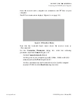
Page 28: ...able and flow control if applicable display in the lower left corner of the main window of PCView A timer begins to count up in the lower right corner as well Figure 2 3 Figure 2 3 PCView Connection Established LGG100 Receiver Setup This section assumes you have already configured your receiver using PCView 1 Place the LGG100 on the appropriate position 2 Center the receiver over the point at whic...

Page 29: ...tion using PCView take the following steps 1 Set up the Base station receiver s antenna as described in LGG100 Receiver Setup on page 2 4 2 Connect an external modem to port B for the LGG100 receiver 3 Turn on the receiver 4 Check the LED for tracked satellites 5 Connect your receiver and computer See Connecting the LGG100 and a Computer on page 2 2 for this procedure 6 Start PCView 7 Click Config...

Page 30: ...nd Alt values Do one of the following If known type in the values Click Get from receiver Enable Averaged and enter the in seconds then click Apply 11 Click Tools Reset receiver and wait until the specified interval span completes Examine the Base coordinates on the Base tab they should correspond to the coordinates obtained from the average 12 Click Refresh if the coordinates are zeros Notice The...

Page 31: ...00 Operator s Manual 2 7 SE TUP AND MEASUR ING DGPS Measuring with the LGG100 Figure 2 5 Base Tab Configuration 13 Select the Ports tab and set the following port parameters Figure 2 6 Figure 2 6 Base Configuration Ports ...

Page 32: ...receiver to modem 14 Click Apply The receiver begins sending data to the selected port Notice Connect the radio antenna before switching the modem to the transmitting mode 15 When finished with the previous steps press the power button on the external modem 16 Select the radio transmission power using the Low High toggle on the rear panel of the modem 17 Use the Channel button to set the frequency...

Page 33: ...er and computer See Connecting the LGG100 and a Computer on page 2 2 for this procedure 3 Start PCView 4 Click Configuration Receiver 5 Select the Positioning tab and set the Position Masks Elevation mask degrees parameter to 15 Figure 2 4 on page 2 6 6 Select the Rover tab and set the desired Positioning Mode Figure 2 8 Figure 2 8 Rover Tab Configuration 7 Select the Ports tab and set the followi...

Page 34: ...ch differential messages will be received from modem Figure 2 9 Rover Configuration Ports 8 Click Apply 9 Click OK to close the Receiver Configuration screen 10 On the main screen check the LQ field to ensure the receiver obtains differential corrections Usually the receiver will start to output the coordinates of the antenna s phase center along with the solution type within 10 30 seconds ...

Page 35: ...Operator s Manual 3 1 OPERATION 3 This chapter describes the following standard LGG100 operating procedures Checking an OAF 4 2 Loading OAFs 4 4 Clearing the NVRAM 4 5 Checking Firmware Version 4 6 Loading New Firmware 4 7 ...

Page 36: ...rt PCView 3 Click Tools Receiver Options Figure 3 1 Figure 3 1 Tools Receiver Options The Options Manager screen displays Figure 3 2 on page 3 3 and contains the following information Option name a name description of the option Current the current status of the option Purchased if the option is purchased or not Leased if the option is leased or not Expiration date the date the option will be disa...

Page 37: ... prevent conflicts with serial port management Loading OAFs Javad Navigation Systems dealers provide customers with OAF files For any OAF related questions E mail JNS at options javad com Please have your receiver ID number available see Checking Firmware Version on page 3 5 1 To load a new OAF follow steps one and two in Checking an OAF on page 3 2 2 Click Load at the bottom of the Option Manager...

Page 38: ...g such as almanac and ephemeris data and receiver position The NVRAM also keeps the current receiver s settings such as active antenna input elevation masks and recording interval and information about the receiver s internal file system Even though clearing the NVRAM is not a common nor normally a recommended operation there are times when clearing the NVRAM can eliminate communication or trackin...

Page 39: ...t the clear NVRAM confirmation dialog box Figure 3 4 Tools Clear NVRAM The receiver will automatically disconnect once the NVRAM is cleared Checking Firmware Version Use PCView to check the firmware version of your receiver Notice The LGG100 receiver should be loaded with firmware version 2 3 or newer 1 Connect your receiver and computer See Connecting the LGG100 and a Computer on page 2 2 for thi...

Page 40: ...and then click File Disconnect to prevent conflicts with serial port management Loading New Firmware Base and Rover receivers must be loaded with the same firmware version Use the latest firmware version available for download from the JNS website to ensure your receiver has the most recent updates Firmware is released as a compressed file that you download and decompress This file contains the fo...

Page 41: ...tp www javad com 1 Download and install FLoader if applicable 2 Download the new firmware package to your computer 3 Physically connect your receiver and computer using the RS232 cable 4 Activate FLoader Figure 3 7 Figure 3 7 Floader Main Screen 5 On the Connection tab select the COM port on your computer that connects with your receiver and select its speed usually 115200 6 Select the Device tab ...

Page 42: ...e for and select the receiver board s RAM file and Flash file Figure 3 9 10 Click Load and wait until 100 of the files load into your receiver Notice If you selected an incorrect RAM or Flash file an error message displays at the bottom of the dialog box Reselect the correct file 11 Click File Exit 12 Clear the receiver s NVRAM see Clearing the NVRAM on page 3 4 and update the almanac after loadin...

Page 43: ... have few problems with your LGG100 This chapter will help you diagnose and solve some common minor problems you may encounter with your LGG100 receiver This chapter provides the following sections Things to Check First 5 2 Receiver Problems 5 3 Obtaining Technical Support 5 7 Chapter Tip For assistance with complex problems see Obtaining Technical Support on page 4 6 ...

Page 44: ...ck the cables Cables became defective more often than the devices do Check the sections below for available solutions Reset the receiver using PCView Tools Reset receiver Restore factory default settings using PCView click Configuration Receiver then Set all parameters to defaults Clear the NVRAM see Clearing the NVRAM on page 3 4 Initialize the file system click Tools Initialize file system this ...

Page 45: ...8 and Connector Specifications on page B 4 for information on the receiver s connectors The cable is damaged Use an undamaged cable Contact your Dealer to replace the cable The receiver port used for connection is not in Command mode Connect your receiver and a computer using a free port see Connecting the LGG100 and a Computer on page 2 2 and start PCView Click Configuration Receiver Ports Change...

Page 46: ...erential solutions Causes Solutions Incorrect Base coordinates entered Specify the correct coordinates for the Base station using PCView or other suitable field data collection software The receiver is not configured as a Base or Rover If the receiver should function as a Base ensure it has the proper configuration See DGPS Measuring with the LGG100 on page 2 5 for further information If the recei...

Page 47: ...amaged Check the cable connector attachment to the receiver Remove and reattach the cable connector to ensure a secure connection The Base and Rover modems are set to different radio channels Set the Base and Rover receivers to the same radio channel A discrepancy exists between the differential standards used at the Base and Rover receivers Ensure the Base and Rover receivers use the same correct...

Page 48: ...d com Ensemble ensemble javad com PCView pcview javad com FieldView fieldview javad com If in doubt which e mail address to use for your particular question please send it to support javad com The specified baud rate is not compatible with the baud rates the modem supports The baud rate is the rate at which the receiver transmits differential messages to the modem and vice versa Change the baud ra...

Page 49: ...pport Website The Javad Navigation Systems website provides current information about JNS s line of products The support area of the website provides access to frequently asked questions configuration procedures manuals etc To access the JNS website home page use http www javad com ...

Page 50: ...4 8 LGG100 Operator s Manual www javad com Notes ...

Page 51: ...nformation on script files see the PCView Software Manual 1 Connect your receiver and computer See Connecting the LGG100 and a Computer on page 2 2 for this procedure 2 Start PCView 3 Click on File Manual Mode 4 Click Edit script 5 Navigate to the folder in which you want to save the script file 6 Type the file name All files have a jpc extension For example Daisy_38400 jpc to enable the daisy cha...

Page 52: ...et dev ser c imode echo set cur term eoff QUIT set cur term echo dev null set cur term imode echo set cur term echo dev ser c QUIT set cur term imode cmd set dev ser c echo dev null set dev ser c imode cmd set dev ser c rate 38400 set cur term rate 115200 9 Click Save script 10 Click Close editor Once you have created a script file 1 Click Load script on the Manual Mode dialog box 2 Navigate to th...

Page 53: ...nts General Details Table B 1 lists receiver component details Table B 1 LGG100 General Specifications Physical Enclosure Aluminum extrusion waterproof Color JNS Green and black Dimensions W 150 x H 85 x D 35 mm Weight 0 310 kg LED Satellites status Environment Operating temperature 30 C to 80 C Storage temperature 40 C to 80 C Humidity 95 non condensing ...

Page 54: ... Up to 100 Hz update rate for real time position and raw data code and carrier RTCM 104 version 2 3 2 2 Technology Low signal tracking Advanced Multipath mitigation WAAS Data Output Real time data outputs RTCM 104 version 2 2 2 3 ASCII Output NMEA 0183 version 3 0 Other Outputs JNS format Output Rate Up to 100 times per second 100Hz Measuring Mode DGPS Differential GPS Cold Start Warm Start Reacqu...

Page 55: ...1 Tracking Channels 50 Tracked Signals L1 C A and Carrier Tracking Functions Multi path reduction Code Smoothing interval Code and Carrier WAAS EGNOS Standard PPS Output optional Number of PPS ports 1 Edge Rise Fall Period 10 to 1000000000 ms Offset 500000000 to 500000000 msec 500000 to 500000 nsec Reference time GPS GLONASS UTC USNO UTC SU Event Marker optional Number of Event Marker ports 1 Edge...

Page 56: ...The power connector Figure B 1 is a sealed receptacle 5 pin ODU p n G80F1C T05QF00 0000 Figure B 1 Power Connector Table B 3 gives power connector specifications Table B 3 Number Signal Name Dir Details 1 Power_INP P 9 to 35 volts DC input 2 Power_INP P 9 to 35 volts DC input 3 Power_GND P Ground power return 4 Power_GND P Ground power return 5 Not used ...

Page 57: ...ons Table B 4 Number Signal Name Dir Details 1 Power_OUT P Power Output supplied voltage 2 GND Signal ground 3 CTS I Clear to send 4 RTS O Request to send 5 RXD I Receive data 6 TXD O Transmit data 7 Not used GPS External Antenna RF Connector The external antenna connector type Table B 5 is a TNC RF connector with an Applied Engineering Product part number 6001 7051 003 Table B 5 Type Signal Name ...

Page 58: ...B 6 LGG100 Operator s Manual www javad com APPENDIX Specifications B ...

Page 59: ...s and depths This product should never be used Without the user thoroughly understanding this manual After disabling safety systems or altering the product With unauthorized accessories Without proper safeguards at the measuring site Contrary to applicable laws rules and regulations DANGER THE LGG100 SHOULD NEVER BE USED IN DANGEROUS ENVIRONMENTS USE IN RAIN OR SNOW FOR A LIMITED PERIOD IS PERMITT...

Page 60: ...shipped without proper packaging or otherwise treated without care erroneous measurements may occur The owner should periodically test this product to ensure it provides accurate measurements Inform JNS immediately if this product does not function properly CAUTION Only allow authorized JNS warranty service centers to service or repair this product ...

Page 61: ...ervice to repair damage to the product resulting from an accident disaster misuses abuse or modification of the product Warranty service may be obtained from an authorized JNS warranty service dealer If this product is delivered by mail purchaser agrees to insure the product or assume the risk of loss or damage in transit to prepay shipping charges to the warranty service location and to use the o...

Page 62: ...LGG100 Operator s Manual Rev A 08 06 2006 Javad Navigation Systems All rights reserved No unauthorized duplication ...

Reviews: