41
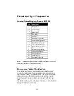
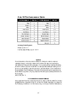
9-to-15 Pin Conversion Table
9 PIN SIGNALS
PIN NO.
15 PIN SIGNALS
PIN NO.
Red
1
Red
1
Green
2
Green
2
Blue
3
Blue
3
Horz Sync
4
Horz Sync
13
Vert Sync
5
Vert Sync
14
Red Ground
6
Return Red
6
Green Ground
7
Return Green
7
Blue Ground
8
Return Blue
8
Sync Ground
9
Digital Ground
10
Ground
5
Analog Video Signals
Black Level = 0 V
Full Intensity (White) Level = +0.7 V
NOTICE
The information in this document is subject to change in order to improve
reliability, design, or function without prior notice and does not represent a
commitment on the part of the company. In no event will the company be liable
for direct, indirect, special, incidental, or consequential damages arising out of
the use or the inability to use the product or documentation, even if advised of
the possibility of such damages. No part of this manual may be reproduced or
transmitted in any form or by any means without the prior written permission of
the company.
AUG 1999, Rev. A
FCC SHIELDED CABLE WARNING:
This equipment has been tested and found to comply with the limits for a Class
B digital device, pursuant to Part 15 of the FCC Rules.
Operation is subject to
the following conditions: (1) this device may not cause harmful interference,
Summary of Contents for 3DForceS-128
Page 12: ...12 2 Click on Next 3 Click on Next again...
Page 13: ...13 4 Click on Next to continue 5 Wizard has transmit all files now...
Page 15: ...15 1 Click on Display Driver text to start the installation...
Page 20: ...20 3 Click on Next 4 Checked Typical then click on Next...
Page 21: ...21 5 Click on Next again 6 Click on Next on this confirmation screen...


