background image

Installation

5

Unpacking

Check the packaging for any signs of damage.

Carefully remove the machine and retain the packaging until 
the installation is complete.

Location

The  machine  should  be  located  in  a  suitable  position  and 
environment. Care should be taken to avoid moisture, dust, 
steam, oil or corrosive gases

Place  on  a  secure  level  surface  and  ensure  that  there  is 
adequate  clearance  around  the  machine  to  ensure  natural 
airflow.

Input connection

Before  connecting  the  machine  you  should  ensure  that  the 
correct  supply  is  available.  Details  of  the  machine 
requirements can be found on the data plate of the machine 
or in the technical parameters shown in the manual.

The equipment should be connected by a suitably qualified 
competent  person.  Always  ensure  the  equipment  has  a 
proper grounding.

Never  connect  the  machine  to  the  mains  supply  with  the 
panels removed.

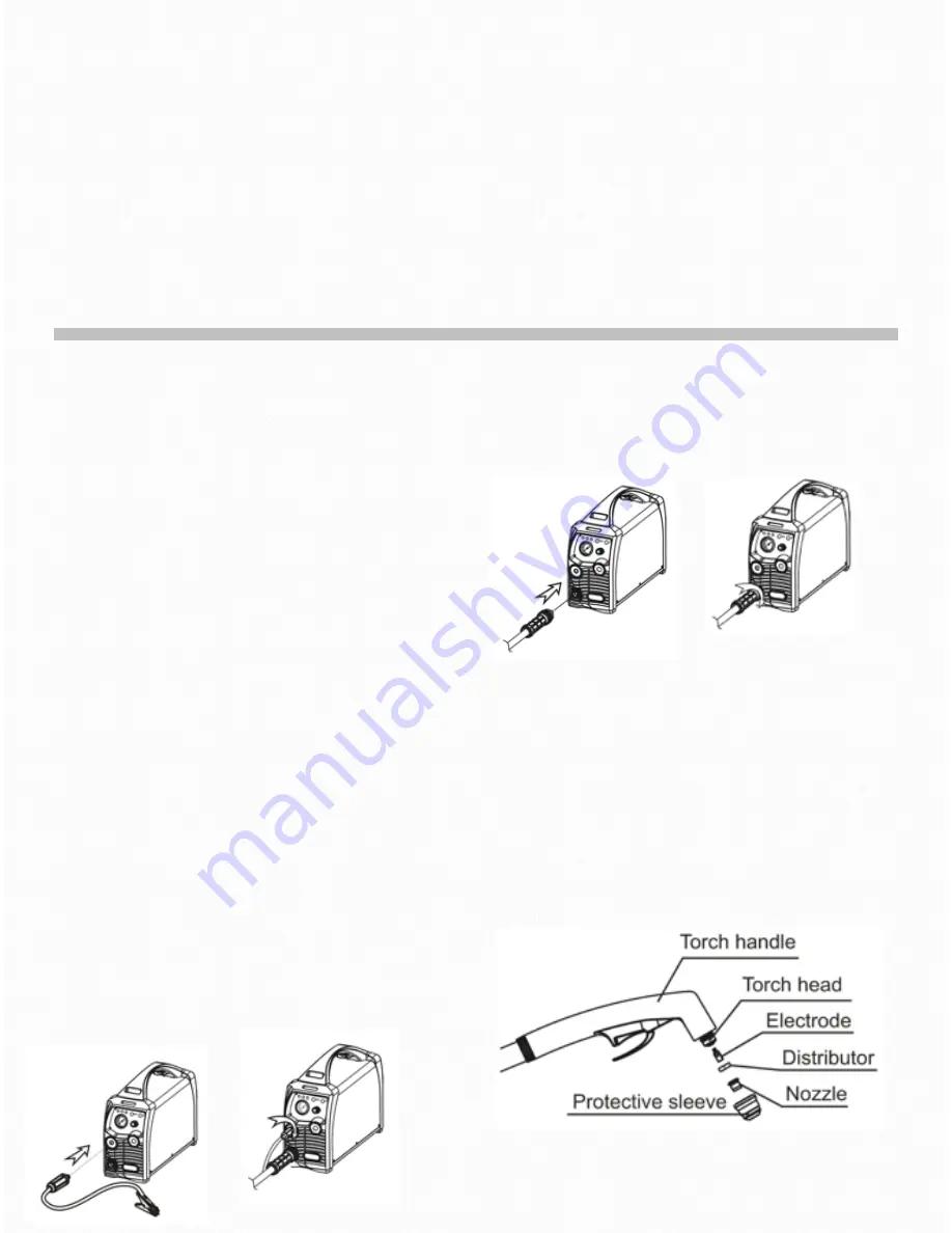
Connection of work cable

Insert the quick plug on the work cable into the quick socket 
at the bottom of the front panel of the machine, and tighten 
it  clockwise.  Clamp  the  workpiece  with  the  work  clamp  at 
the other end of the earth cable.

Connection of cutting torch


Connect the central connection plug on the cutting torch to 
the central connection socket of the power supply, and 
tighten It clockwise to avoid gas leakage.

Installation of the cutting torch

1)


Screw the end of the electrode with screw thread into 

the torch head, and tighten it.
2)


Insert the other end of the electrode into the 

distributor.
3)


Connect the nozzle with the electrode and distributor.

4)


Connect the protective sleeve with the nozzle, screw 

it into the torch head, and tighten it.
Note: Screw the electrode into the torch with an inner 
hexagon spanner, and tighten it. Otherwise, the inner thread 
of the electrode will be burned.

9

Summary of Contents for Cut 45P

Page 1: ...wilkinsonstar com Cut 45P Air Plasma Cutting machine Order code JP 45P OPERATOR MANUAL ...

Page 2: ...upplier of equipment in the UK and our products are supported by our extensive service network Call your distributor in the unlikely event of a problem occurring Please record below the details from your product as these will be required for warranty purposes and to ensure you get the correct information should you require assistance or spare parts Date purchased __________________________________...

Page 3: ...ye protection Insulate yourself from work and ground using dry insulating mats or covers big enough to prevent any physical contact with the work ground Never touch the electrode if you are in contact with the work ground or another electrode from a different machine Do not wrap cables over your body Ensure that you take additional safety precautions when you are welding in electrically hazardous c...

Page 4: ... fan may cut fingers and hands and snag garments Protections and coverings may be removed for maintenance and controls only by qualified personnel after first disconnecting the power supply cable Replace the coverings and protections and close all doors when the intervention is finished and before starting the equipment Take care to avoid getting fingers trapped when loading and feeding wire durin...

Page 5: ...network at the public network connection point must be applied to these systems In this case the installer or the user is responsible for ensuring the equipment can be connected consulting the electricity provider if necessary Materials and their disposal The equipment is manufactured with materials which do not contain any toxic or poisonous materials dangerous to the operator When the equipment ...

Page 6: ...eyond audio range which almost eliminates the noise pollution High consistency and stable performance Generally speaking for a cutting machine with analogue circuit control the performance characteristics are determined by the parameters of various components Cutting performance of the machines differ as a result of the inconsistent parameters of the components so even for the cutting machines of t...

Page 7: ...0V AC 15 Rated input frequency Hz 50 60 Rated input capacity KVA 5 1 Recommended supply fuse A 20 Compressed air requirement 0 45Mpa 170L Min No load voltage 280V DC Cutting current A 20 45 Rated output voltage V 98 Rated duty cycle 45A 35 Efficiency 85 Power factor 0 99 Insulation class F Protection class IP21S Arc ignition Without HF Maximum cutting thickness mm 19 Weight kg 9 2 Overall size mm L ...

Page 8: ...Controls 4 PANEL LAYOUT FRONT REAR 7 1 AIR PRESSURE GUAGE 5 MAINS INPUT CABLE 2 WORK RETURN CONNECTOR 6 MAINS ON OFF SWITCH 3 TORCH CONNECTOR 7 AIR INLET CONNECTION 4 CURRENT CONTROL KNOB ...

Page 9: ...sumable parts of the machine are incorrectly fitted or the torch head is shorted When in this state the machine stops working 4 2T indicator It illuminates when the machine is in 2T status 5 4T indicator It illuminates when the machine is in 4T status 6 Gas check indicator It illuminates when the machine is in gas check status At this moment the machine cannot cut 7 Metal mesh cutting indicator Th...

Page 10: ...per grounding Never connect the machine to the mains supply with the panels removed Connection of work cable Insert the quick plug on the work cable into the quick socket at the bottom of the front panel of the machine and tighten it clockwise Clamp the workpiece with the work clamp at the other end of the earth cable Connection of cutting torch Connect the central connection plug on the cutting t...

Page 11: ...ust the gas pressure to the desired value by rotating the knob rotate to direction to increase gas pressure rotate to direction to reduce gas pressure Press down the pressure control knob to lock the adjusting knob Any water will be drained automatically via the auto drain function in the embedded filter reducer Ensure the mains supply is disconnected whilst replacing the cover Over current over v...

Page 12: ...d due to the fact that the inner resistance of the cable will reduce the output voltage Notes for cutting operation 1 Do not touch the hot workpiece with bare hands to avoid burning 2 It is recommended not to ignite the arc in the air if not necessary for it will shorten the lifespan of the electrode and nozzle of the torch 3 It is recommended to initiate the cutting from the edge of workpiece unl...

Page 13: ... check for any warning Led s and general operation Monthly examination Using the dry compressed air to clean the inside of arc welding machine Especially check for build up of dust debris on intake grills main voltage transformer inductance IGBT modules the fast recover diode and PCB etc Take care when blowing electronic components and do not dislodge any wiring connections Check the security of o...

Page 14: ...Electrical schematic 7 13 ...

Page 15: ...Parts list 8 Cut 45P JP 45P 14 ...

Page 16: ...8681 Display panel 27 10037075 Insulating strip 9 10007295 Pressure guage 28 10050319 Main PCB 10 10041712 Jasic ident 29 10050326 Insulation 11 10037152 Quick connector socket 30 10037028 Support 12 10043926 Blanking plate 31 10048706 Base plate 13 10048633 Central connector 32 10006256 Rectifier 14 10050205 PFC inductance 33 10043394 Diode 15 10048682 Base panel 34 10050257 Heatsink 16 10048661 ...

Page 17: ...JP 45P AIR PLASMA CUTTING MACHINE Order code JP 45P Wilkinson Star Limited Issue 1 November 2014 Product is subject to change without notice xvi ...

Reviews: