


5
For Additional Support Call: 866.393.4202 or Email: [email protected]
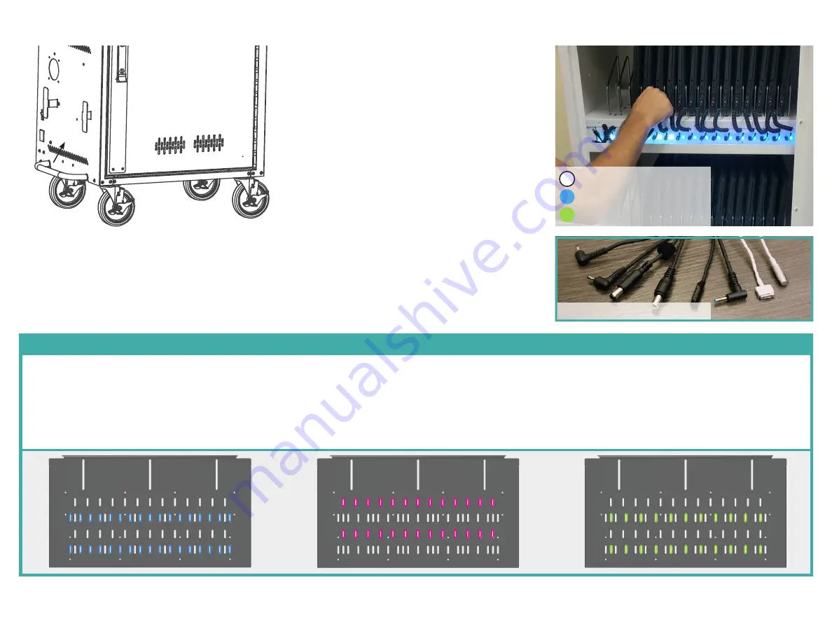
Elevate carts feature adjustable device bays with multiple configuration options. This means that not every slot in the tray will have a divider in it and there may be
extra, unused dividers at the end of the assembly process depending on which hole pattern is used. Use the guides below to determine which hole pattern to use.
To install the dividers, simply place the tall side of the divider into the rear slot first, then push in and down to get the other side into the front slot.
32 DEVICE PATTERN
Best for devices up to 1” wide.
24 DEVICE PATTERN
Best for devices up to 1.25” wide.
20 DEVICE PATTERN
Best for devices up to 1.5” wide.
Installing Device Bay Dividers
17:
Plug in the external power cord into the cart and to a
power source. The switch on the side of the cart and
the USB-C hub(s) inside should illuminate. If they do
not, check all power connections and try flipping the
switch. Disconnect from the wall outlet and wrap the
power cable around the brackets for transportation.
· Plug the power cable into a standard 15A outlet. Be
sure that the power switch on the side of the cart is in
the ON position. LEDs will illuminate white to indicate
the cart is connected to a power source.
· Power down devices, then connect them to the USB-C
charging cables.
· You may hear a clicking sound, and the LED lights
will change color according to the power draw of the
attached devices.
· The system will automatically limit power consumption
by turning some of the USB-C ports off temporarily.
Refer to the device itself for the level of charge.
· The devices will charge as quickly and evenly as
possible, up to 65W, without drawing too much power.
· Devices that do not feature a USB-C charging port
can be charged using USB-C emulator cables. (Not
Included, contact JAR Systems for more info)
3
2
5
4
6
N/A
(A1)
(C3) x4
(A1)
(A1)
(A1)
(C3) x4
1
(A1) x12
(C3) x4
Using the Cart
White: Port Ready
Blue: Device Charging
Green: Charge Level >90%
USB-C Emulator Cables


