emPC-X1600
(
Hardware Manual
)
•
Interfaces
4 - 11
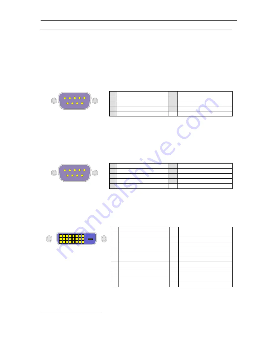
table 5: RS232 connector
4.4 RS485
In the RS485 variant, there are only the differential signals D+ and D- provided. The transceiver is
enabled to send data, when RTS# of the corresponding UART is low. Data received on the RS485 will
always be seen on the UART’s RxD input. This is regardless of the RTS# state. It is however possible to
modify the hardware, so that transmitted data is not received (RTS# low disables receiver).
When the receiver is enabled and no data is send (MARK=1), then D+ > D-.
1 n.c.
6 GND
2 B / D+
7 A / D-
3 GND
8 n.c.
4 n.c.
9 n.c.
5 n.c.
9pin male D-Sub
table 6: RS232 connector
1
6
4.5 CAN
The CAN interface is implemented with a SJA1000 controller chip. The connector is a standard 9 pin D-
SUB plug with a pin out shown in table 7. The CAN interface is isolated and has a software switchable
120 Ohm termination.
1 n.c.
6 GND
2 CANL
7 CANH
3 GND
8 n.c.
4 n.c.
9 VEXT
1
5 n.c.
9pin male D-Sub
table 7: CAN connector
1
6
4.6 DVI-D
connector
Digital graphics connector from motherboard. Analog graphic signals are not available on this port.
1 TMDS 2-
13 TMDS 3+
2 TMDS
2+
14 +5V
3 SHIELD
15 GND
4 TMDS 4-
16 Hotplug detect
5 TMDS 4+
17 TMDS 0-
6 DDC clock
18 TMDS 0+
7 DDC
data
19 SHIELD
8 N/C
20 TMDS
5-
9 TMDS 1-
21 TMDS 5+
10 TMDS
1+
22 SHIELD
11 SHIELD
23 TMDS
C+
12 TMDS 3-
24 TMDS C-
table 8: DVI-D connector
Rev. 1.1
©
Janz Tec AG
1
This signal is optionally available to provide power to supply an external transceiver module
Summary of Contents for emPC-X1600
Page 6: ......


