


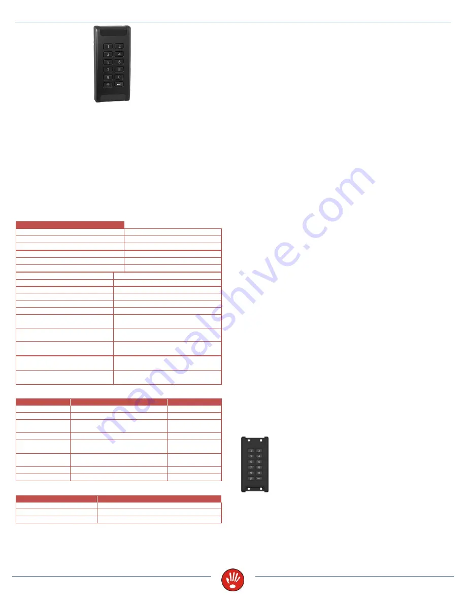
REX K-1-9 and REX K-3-9 – Standalone or access controller
3/2015
Black line
www.jantar.si
REX K-1-9 and REX K-3-9 – STANDALONE OR ACCESS
CONTROLLER
The Rex is a controller with built-in proximity card reader and keypad. It is
designed for residential and business buildings, offices, shops, etc. In various
operation modes, the controller allows access for up to 500 users (2 master
cards or codes + 500 user cards or codes). The controller can have 125kHz
or 13.56MHz reading frequency.
As a standalone controller, the entire set-up procedure is carried out with
master card or code. User cards and codes can either be registered or
deleted.
As an access controller, the entire set-up procedure is carried out with the
software.
The controller signals normal operation with flashing red and green LED It
can also be used as a Wiegand 26-bit reader, if needed.
TECHNICAL DATA
REX K
REX K-1-9 reading frequency
125kHz
REX K-1-9 reading distance
Up to 13cm
REX K-1-9 current consumption
60mA
REX K-3-9 reading frequency
13.56MHz
REX K-3-9 reading distance
Up to 7cm
REX K-3-9 current consumption
90mA
Dimensions (mm)
58x120x17 (WxHxD)
Protection
IP65
Communication
RS485
Operating voltage
From 9V to 14V DC
Operating temperature
From -20°C to 70°C
Cabel
Flat cable 20cm
Memory
500 cards or codes
500 events
Inputs
Door status
Push button
Outputs
Transistor output for el. strike 0.5A
Clock
Real time clock, battery backup
(max. ten hours)
Keypad
Numeric, illuminated, with gold
plated contacts
CONNECTION CABLE
Wire-Color
Description/Wiegand 26-bit
Specification
1 – red
9-14V DC
Power supply
2 – gray
GND
Ground
3 – gray
El. strike output / Data 0
Max. 0.5A
Active = GND
4 – gray
Alarm output/ Data 1
Active = GND
5 – gray
Door status switch input/ Buzzer
input
Active = GND
6 – gray
Push button input /
LED input
Active = GND
7 – gray
CA
RS485 A line
8 – gray
CB
RS485 B line
LED DIODES
Color
Description
Flashing red/green
Normal mode
Lit green
El. strike is unlocked
Lit red
Card has no rights
Power supply
The controller need’s external power supply to operate. The Spider W40
power supply is sufficient to power two controllers and two 12V electric
strikes or two 12V magnetic locks (0.5A). If you will use it as a standalone
controller and low consumption electric strike (0.25A) you can use power
supply Spider W5.
Voltage drops and cable signal interferences
When you connect the controller, use cable with a diameter of at least
0.22mm
2
. If the cable length exceeds 25m, use one twisted pair of UTP
cables for the positive (+) pole and one for the negative (-) pole. The cable
length between power supply and the controller should not exceed 50m.
Take into consideration that a 0.22mm
2
cable has a resistance of
approximately 9 ohm per 100m. The power supply at the end of cable should
be a minimum of 9V. If you are using el. strike, it is highly recommended
that the voltage drop is calculated. At greater distances, a thicker cable of
0.5mm
2
or more should be used wherever possible.
If the load is, for example, 0.5A (with el. strike) then, on the 0.22mm
2
cable
voltage drop will be 4.5V at 100m. For the device with 60mA consumption,
the voltage drop is 0.5V.
Reading distance depends on where the controller is installed. The presence
of metal or interferences can significantly reduce the reading distance.
DO
NOT
install the controller directly on metal surfaces and/or cover it with a
metal cover.
It is
not recommended
to install controllers closer than
30cm
from each
other in any direction. Otherwise, it may result in inaccurate readings or,
indeed, in the controller
not reading at all
.
For the Rex K-3-9 to comply with EMC directives (CE), you have to
put ferrite core on the cable as close to the controller as possible,
making two turns!
Inputs, outputs and environment
Inputs:
Inputs are realized with opto-isolators. The input is active, when pulled to
ground with an open collector transistor or mechanical switch, which is
connecting the input pin of the controller to the Ground.
Outputs:
Output has a pre-installed protection diode for an inductive load. It is also
protected from current overload. The best way is to use a 0.25A el. strike or
a 0.5A el. magnet, which has to be connected to the same positive pole (+)
as the controller. Connect the negative pole (-) to the door strike output
(wire 3). When the output is active it is pulled to ground. This can be
changed with function 5 – negate output (for el. magnet).
Environment:
If the plastic housing is in a different color than black, then there is a chance
that the color will change (to some extend) in a few months or years if
exposed to direct sunlight.
The controller has IP65 protection, but you must
assure good cable joints, protected against moisture, otherwise corrosion
may damage the controller. Damage in such cases is not covered by the
warranty.
Reading range:
The controller has a program algorithm that, at power start, sets parameters
based on the installation environment, so as to ensure an optimal reading
range.
DO NOT
install the controller directly on metal surfaces and/or cover
it with a metal cover; it may stop working/reading. If you plan to test the
controller and move it onto different surfaces, then you have to reset it
(power off/on) on each surface.
Installation of Rex K
Remove black plastic screw covers on the top and the bottom of
the controller. Install the controller
to the wall with two supplied
screws. Use diagonal holes - it enables a small correction of the
position of the controller (up, down, left, right). When the
controller is installed, put the screw covers back on
.