22
MO200
5200QDC
CORRECT RESULTS
The display shows "Sensor" and the
machine beeps.
• When the buttonhole lever is pulled, the
screen displays "BH:H".
• When the buttonhole lever is positioned
in center, the screen displays "BH:L".
• When the buttonhole lever is pushed,
the screen displays "BH:H".
Each time the twin needle button is
presses, the screen displays
NP1:ON
NP2:ON or OFF
NP1:ON
NP3:OFF
NP4:OFF
NP1:ON
in order.
• When needle is in the highest position,
the screen displays "Bsen:H, Fsen:L".
• When needle is in the lowest position,
the screen displays "Bsen:L, Fsen:H".
Each time the stock call button is
pressed, the screen displays
M:ON
MR:OFF
ML:OFF
M:ON
in order.
Press
CLR
button to proceed to the next
step.
The display shows "Velocity Seneor" and
the machine beeps.
• The value should be 370 to 376 when
the handwheel is rotated once.
Press
CLR
button to proceed to the next
step.
The display shows "Volume" and the
machine beeps.
• When the speed control lever is at left,
the screen displays "000" to "010".
• When the speed control lever is at right,
the screen displays "255" to "250".
Press
CLR
button to proceed to the next
step.
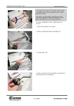
TESTS
Lower the buttonhole lever.
Pull, and push the buttonhole lever,
then check the display.
"Twin needle button" is pushed,
then check the display.
Turn the handwhell toward you to
move the needle from highest to
the lowest position.
Check the screen.
Turn the handwheel clockwise one
complete turn.
Set the speed control to the
leftmost position.
Then slide the speed control lever
from left to right, then return to left.
4)
BUTTONHOLE
SENSOR
NEEDLE PLATE
SENSOR
UPPER-SHAFT
SENSOR
5)
VELOCITY
SENSOR
(DC MOTOR)
6)
SLIDE VOLUME
DEFECTIVE RESULTS /
REPLACEMENT AND
ADJUSTMENT
DEFECTIVE RESULTS:
• The display does not change or
show the correct results.
REPLACE OR ADJUST:
• Adjust the position of the shield
plate.
• Adjust the position of the
photosensor.
• Replace the photosensor.
• Replace the board A.
DEFECTIVE RESULTS:
• The value does not change.
REPLACE:
• Cleaning of velocity sensor slit.
• Adjust the velocity sensor.
• Replace the DC motor.
• Replace the board A.
DEFECTIVE RESULTS
:
• The value does not change.
• The value does not match with
the correct results.
REPLACE:
• Adjust the slide volume.
• Replace the DC motor.
• Replace the board A and board K.
SELF DIAGNOSTIC TESTS