background image

MECHANICAL ADJUSTMENT

NEEDLE TO ROTARY HOOK TIMING

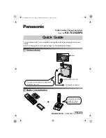
With the needle bar swing to the left at the maximum zigzag width, the amount of ascending
travel of the needle bar from its lower position (H) to the position where the tip of the rotary
hook (F) exactly meets the right side of the needle should be 3.15 to 3.45mm (G).

Before the adjustment, be sure to check the needle bar height.

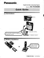
1. Select pattern No. 3 and set the zigzag width at ”6.5”.
2. Remove screw (A) to remove the needle plate (B) and bobbin holder (C).
3. Remove the bed cover (See page 6).
4. Loosen set screws (D) on the lower shaft gear (E).
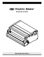
5. Turn the hand wheel toward you to raise the needle bar 3.15 to 3.45mm from its lowest

position with the needle swing to the left.

6. While holding the hand wheel by hand to prevent the needle bar from moving, turn the

lower shaft gear in the arrow direction until the tip of the rotary hook exactly meets the
right side of the needle.

7. Tighten the set screws on the lower shaft gear.
8. Attach the bed cover, bobbin holder and needle plate.

18

Summary of Contents for DE 5024

Page 1: ...SERVICING MANUAL DE 5024...

Page 2: ...1 NEEDLE POSITION 12 DISTRIBUTION OF NEEDLE SWING 13 ZIGZAG STOPPER 14 NEEDLE CLEARANCE TO ROTARY HOOK 15 BACKLASH LOWER SHAFT GEAR 16 NEEDLE BAR HEIGHT 17 NEEDLE TO ROTARY HOOK TIMING 18 FEED DOG HEI...

Page 3: ...EDLE FABRIC 6 INAPPROPRIATE NEEDLE SEEMECHANICAL P 17 BARHEIGHT ADJUSTMENT NEEDLEBARHEIGHT 7 INAPPROPRIATE NEEDLE SEEMECHANICAL P 18 TOHOOKTIMING ADJUSTMENT NEEDLE TO ROTARY HOOK TIMING 8 INAPPROPRIAT...

Page 4: ...NHOLDER BOBBIN BOBBINHOLDER CORRECTLY THREAD 2 TOOMUCHTHREADIS ADJUSTTHEPOSITIONOFBOBBIN AROUNDONTHEBOBBIN WINDERSTOPPER 3 LINTISSTUCKINSIDETHE CLEAN THE BOBBIN HOLDER BOBBINHOLDER 4 THREAD QUALITY IS...

Page 5: ...CH UPPER SHAFT PLAY REDUCETHEUPPERSHAFTPLAY 3 INAPPROPRIATEBELT SEEMECHANICAL P 25 TENSION ADJUSTMENT MOTORBELT TENSION 4 UPPER SHAFT GEAR IS LOOSE ELIMINATETHELOOSENESS 5 NOTENOUGHOIL OIL ALL MOVING...

Page 6: ...ays G from each pin H by pushing them from both sides 3 Detach the top cover together with the carrying handle TO ATTACH 4 Put the top cover and carrying handle together and fit the carrying handle st...

Page 7: ...SERVICE ACCESS BELT COVER TO REMOVE 1 Remove the top cover See page 4 2 Loosen the screws A and B from the front cover 5...

Page 8: ...SERVICE ACCESS BASE 1 Remove 4 screws A 2 Remove the base B BED COVER 1 Remove 2 screws D 2 Remove the bed cover E When you replace the bed cover set the drop lever F in the left position 6...

Page 9: ...the pattern selector dial you can see the position of screw D 3 Remove the screws A and B then loosen the screws C D and E 4 Push and lower the part F gently then pull it toward you to replace the fro...

Page 10: ...n should be 75 to 90 g with the thread tension dial set at 3 ADJUSTMENT PROCEDURE 1 Set the thread tension dial B at 3 and pass the thread as shown 2 Open the face cover and lower the pressure foot 2...

Page 11: ...ows ADJUSTMENT PROCEDURE 1 Open the face cover 2 Raise the presser foot lever B and loosen the hexagonal socket screw D on the presser bar bracket E 3 Adjust the distance between the zigzag foot A and...

Page 12: ...3 Simple zigzag 2 Turn the hand wheel by hand 3 The needle should not swing side to side at this setting ADJUSTMENT PROCEDURE 1 Remove the top cover See page 4 2 Loosen screw A 3 Move the zigzag width...

Page 13: ...ce carefully turn the hand wheel and adjust so that lateral needle swing starts from a position 2 to 3mm above the needle plate in right outflow E Note Make sure the worm does not move sidewise when t...

Page 14: ...should not move when you turn the stitch width control to 0 ADJUSTMENT PROCEDURE 1 Remove the top cover See page 4 2 Turn the hand wheel toward you until the needle comes to the center of the slit in...

Page 15: ...o mark the needle point A on a piece of paper by turning the hand wheel 6 Raise the needle to its highest position 7 Turn the stitch width control to 6 5 8 Lower the needle to mark needle points B and...

Page 16: ...wheel until the needle tip is located above the top surface of the needle plate in descending travel at the right needle position 4 Slightly loosen screw A lightly press the stopper B against the zigz...

Page 17: ...needle bar reaches its lowest position 5 The clearance between the master needle D and the tip of the rotary hook E should be between 0 10 and 0 05 mm ADJUSTMENT PROCEDURE 1 Remove the bed cover See p...

Page 18: ...se and counterclockwise by hand and check the play J It should be within 0 8 mm If there is more than 0 8mm backlash between the gears adjust as follows ADJUSTMENT PROCEDURE 1 Remove the bed cover See...

Page 19: ...ct pattern No 3 and set the zigzag width at 6 5 2 Remove the set screw A to remove the needle plate B and bobbin holder C 3 Turn the machine to the back and open the face cover 4 Turn the hand wheel t...

Page 20: ...zigzag width at 6 5 2 Remove screw A to remove the needle plate B and bobbin holder C 3 Remove the bed cover See page 6 4 Loosen set screws D on the lower shaft gear E 5 Turn the hand wheel toward you...

Page 21: ...sure dial at 3 and lower the presser foot 2 Turn the hand wheel until the feed dog comes to its highest position 3 Remove the bed cover See page 6 4 Loosen screw A and nut B 2 Turn the adjusting screw...

Page 22: ...eding is not balanced make adjustment in the following procedure 1 Remove the top cover See page 4 and set the stretch stitch adjusting knob E at the setting mark F 2 place a piece of paper under the...

Page 23: ...ht side and left side of buttonhole 4 The correct buttonhole stitch balance is when there is the same density on the right and left sides of the buttonhole ADJUSTMENT PROCEDURE 1 Remove the bed cover...

Page 24: ...you turn the hand wheel toward you 4 The machine should not feed a piece of paper at this setting ADJUSTMENT PROCEDURE 1 Remove the belt cover See page 5 2 Select pattern No 1 straight stitch and set...

Page 25: ...face cover and remove the micro switch 3 Loosen screw A 4 Pull down the buttonhole lever E until it touches foot R and bar B touches the front base plate F Make sure buttonhole lever adjusting plate C...

Page 26: ...is sewn too early F or if bar tack is sewn too late G adjust as follows ADJUSTMENT PROCEDURE 1 Remove the belt cover See page 5 2 Loosen set screw A 3 Make adjustment so that plate C touches plate D w...

Page 27: ...Too loose motor belt tension however may cause the belt teeth on the motor pulley to jump 2 The correct motor belt tension is achieved when the belt pushes in about 7mm 9mm under a pressure of about 3...

Page 28: ...n and lower the threader knob D to its lowest position 2 Remove the screw E to remove the threader plate A TO CHANGE THE NEEDLE THREADER 1 If the hook H of the threader plate F touches the left or rig...

Page 29: ...2 7 WIRING OF MACHINE SOCKET...

Reviews: