Busbar tap-off unit
www.janitza.de
58
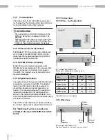
10.10 Device views
10.10.1 View – front and bottom
B
T
B
H
Fig.: Example AKM 96RM-E-125
(device views depending on the device type)
10.10.2 Interfaces
Line
departure
Digital
input
Modbus
interfaces
Ethernet
interface
Fig.: Example AKM 96RM-E-125
(Interfaces depend on the device type and variant)
Type
Width *
(W in mm)
Height *
(H in mm)
Depth *
(D in mm)
AKM xxx-125
530
305
105
AKM xxx-250
662
406
202
AKM xxx-400
862
406
202
AKM xxx-530
862
406
352
10.10.3 Dimensions
* Specifications may vary slightly.
10.11 Communication
The busbar tap-off unit with AKM measurement
technology has the following listed data interfaces
for communication with other instances.
INFORMATION
·The arrangement of the data interfaces on the
AKM can be found in chapter
·Detailed information about communication and
data interfaces can be found in the usage infor-
mation of the installed measurement devices.
10.11.1 Ethernet interface (standard)
The Modbus TCP/IP communication takes place
via an industry standard RJ45 interface, which
leads from the measurement device to an RJ45
connection socket on the AKM.
10.11.2 RS-485 interface (standard)
Mode RTU communication takes place via 2
RS-485 interfaces leading from the measurement
device connections to a socket and a plug on
the AKM. This makes it easy to implement mas-
ter-slave topologies.
10.11.3 Digital input (option)
The digital input of the measurement device is also
provided as a socket on the AKM. The optional
digital input (S0 input) is used, for example, to
record the consumption of compressed air or
coolant. The measured values of the equipment
(consumer) connected to the digital input are
stored in the installed measurement device and
can be evaluated and analyzed, for example, using
the GridVis
®
software.
The AKM with the "digital input" option includes a
24 V power supply unit to supply external devices.
The "Digital Input" option is currently only
available for the types AKM 96RM-E and AKM
96-PA!

