


LX and LT Low NOx Pool/Spa Heater
Page 39
These procedures require a Volt-Ohm
meter with a minimum 0-250VAC voltage range,
and 1-1000 Ohm resistance range. Figure 39
shows the power and control circuits and where
to take measurements. Location numbers in
circles have been added, and will be referenced
in the following sections.
Where test points are shown at circuit board
connectors, the probe of the meter can be carefully
pushed into the connector along side of the wire at the
connection to be measured.
The electrical power supply can be checked with
the heater not set to fire. All other procedures need to
be checked with power correctly supplied to the
heater, all external devices set so that the heater is
allowed to fire and the heater's thermostat set so that
there is a call for heat.
As stated at the beginning of the manual, some of
these procedures are hazardous. Only a qualified
service technician should service the heater.
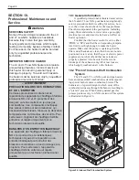
10.5.1 Electrical Power Supply
The electrical components of the LX and LT
Low NOx pool heaters are designed to operate with
supply voltage ranging from 98V to 126V at 60 Hz if
connected to a nominal 115 volt power supply, or 196V
to 253V at 60 Hz if connected to a nominal 230 volt
power supply. Measure supply voltage at the power
supply leads where they enter the heater (identified as
points A, B and C on the wiring diagram in Figure 39.).
Use the voltages in Table 12 to verify that the correct
voltage is supplied to the heater.
If no voltage is present, correct this external
power supply problem to the heater. Circuit breakers,
time clock settings or similar devices may be the
problem. Voltage outside of the above ranges may be
due to poor wiring, poor connections, other loads such
as air conditioning compressors or to an electric utility
company problem. Arrange for correction of the
voltage as appropriate.
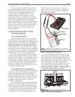
When you are sure that the voltage supplied to
the heater is correct, check the voltage being supplied
to the transformer by the power supply circuit board.
This can be done by measuring the voltage between
the wires of the four-pin connector on the power
supply circuit board. These points are designated as
test points D, E, F, and G on Figure 39. The voltages
measured between any two of these four points will be
determined by the voltage supplied to the transformer
(see Table 13 for expected voltages).
If the voltages measured do not fall within the
limits shown in Table 13, then there is a problem with
the power supply circuit board and the board must be
replaced.
10.5.2 Controller
The controller must be operational in order to
check the control circuits of the heater.
10.5.3 Control Circuit Troubleshooting
The heater controls are arranged in several 24V
60Hz circuits with some operating and safety controls
arranged in series circuits.
Troubleshooting is done by probing for voltage
between the common and various points in the circuit
to determine which component is preventing operation.
Check points are indicated on Figure 39. The black
lead of the meter should be attached to the common
tap on the secondary side of the transformer and may
be left there throughout most of the procedure.
The recommended procedure steps through each
circuit in a sequential way, and each section assumes
that components from all previous sections have been
tested and are operational. However, verifying voltage
at any of the numbered points in that circuit confirms
that all prior components of the circuit are operational.
Table 12. Supply Voltage Measurements
1.
Point A is the ground connection on the heater.
2.
Point B is the location at which the red power lead enters the
power circuit board.
3.
Point C is the location at which the black power lead enters the
power circuit board.
1.
Point D is the location at which the white wire with the black
trace enters the 4 pin connector.
2.
Point E is the location at which the white wire with the red trace
enters the 4 pin connector.
3.
Point F is the location at which the red wire enters the 4 pin
connector.
4.
Point G is the location at which the black wire enters the 4 pin
connector.
Table 13. Voltage Supplied To Transformer
MEASURE
EXPECTED
EXPECTED
BETWEEN
VOLTAGE WITH
VOLTAGE WITH
THESE
230V SUPPLY
115V SUPPLY
POINTS
D and E
0
98 - 126 Volts
D and F
98 - 126 Volts
98 - 126 Volts
D and G
98 - 126 Volts
0
E and F
98 - 126 Volts
0
E and G
98 - 126 Volts
98 - 126 Volts
F and G
196 - 253 Volts
98 - 126 Volts
MEASURE
EXPECTED
EXPECTED
BETWEEN
VOLTAGE WITH
VOLTAGE WITH
THESE
230V SUPPLY
115V SUPPLY
POINTS
A and B
98 - 126 Volts
0
A and C
98 - 126 Volts
98 - 126 Volts
B and C
196 - 253 Volts
98 - 126 Volts