background image

8

Initial Operation / Maintenance

             WARNING  

BE CERTAIN THAT ALL POWER IS SHUT OFF BEFORE SERVICING THE GRAVITY BOX.

Before the gravity box is put into service:

Has the track assembly (opens door) been lubricated for less wear on the sprocket and track and for easier door operation. 

Has the SMV (Slow Moving Vehicle) Emblem been positioned with a point of the triangle upward and as near to the rear and 

centered or as near to the left of center of the unit as practicable? Is it located two to ten feet above the ground measured 

from the lower edge of the emblem?

Has the gravity box been properly attached to the running gear? If no rocking bolster is used, bolt all four corners (use 1/2” 

bolts provided) of the gravity box runners to the running gear. (If the box is used in rough terrain, bolt a minimum of two 

corners and chain (or cable) the remaining corners to allow more box flexibility. 

Have all braces, bolts, nuts, lug bolts, and lug nuts been checked to ensure that they are properly fastened? 


NOTE: The proper torque for the wheel lug nuts is 350 ft lbs. 

Have the safety instructions been read and clearly understood by the operator(s) of this machine. 

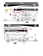
Do the lights work properly? Are all reflective decals clean and visible? Are they positioned correctly?

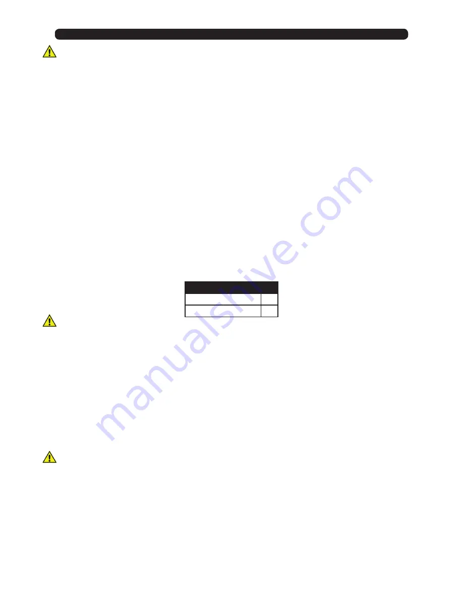
Are the tires properly inflated?  The following is to be used as a 

general guide

 for tire inflation for cyclic use.  Figures can vary 

depending on specific brand of tire used.  

It is important that tires are inspected before and after the unit is loaded.  The 

tire should stand up with no side wall buckling or distress as the tire rolls.


Do Not Exceed The Tire Pressure Indicated 

Below:

BRAKING SYSTEM REQUIREMENTS

             WARNING  Tow Loads Safely

Stopping distance increases with speed and weight of towed loads, and on slopes. Towed loads with or without brakes that 

are too heavy for the tractor or are too fast can cause loss of control. Consider the total weight of the equipment and its load.

For towed equipment WITHOUT brakes, the following is recommended:

Do NOT tow equipment that does not have brakes at speeds over 32 km/h (20 mph); or that, when fully loaded, has a mass 

(weight) over 1.5t (3300 lb) and more than 1.5 times the mass (weight) of the towing unit. 

For towed equipment WITH brakes, the following is recommended:

Do NOT tow equipment that has brakes at speeds over 40 km/h (25 mph); or that, when fully loaded, has a mass (weight) more 

that 4.5 times the mass (weight) of the towing unit. 

Ensure the load does not exceed the recommended weight ratio. Use additional caution when towing loads under adverse 

conditions, when turning and on inclines.

             WARNING

Before filling the gravity box, make certain that no one is inside the grain tank. Never allow children or anyone in, near, or on 

the gravity box during transport or during loading or unloading of grain. Be aware that moving grain is dangerous and can 

cause entrapment, resulting in severe injury or death by suffocation.

After hauling corrosive materials such as fertilizers, be sure to wash out the grain tank to prevent premature rusting. Bare 

spots on metal should be primer coated before applying the outer surface paint.

Check the box periodically for cracks in welds and for other structural damage. Have cracked welds fixed immediately. 

Failure to do so could result in extensive damage and greatly reduce the life of the gravity box.

Tire Size

psi

385/65R22.5

70

425/65R22.5

85

Summary of Contents for 55 Series

Page 1: ...OPERATORS MANUAL J M Mfg Co Inc 284 Railroad Street P O Box 547 Fort Recovery OH 45846 Ph 419 375 2376 Fax 419 375 2708 www jm inc com 455 555 Rev 10 23 2018 Gravity Wagon...

Page 2: ...10 BleedingtheBrakeLines AdjustingtheMasterCylinder 11 Trail Adjustments 12 Running Gear Toe In 14 15 Safety Signs 16 55 Series Tongue Assembly w Brakes 17 16 Ton Running Gear 18 Fender Kit 19 Shell...

Page 3: ...air ii accident abuse or improper use iii improper or insufficient maintenance or iv normal wear or tear This warranty does not cover products that are previously owned and extends solely to the origi...

Page 4: ...re used in conjunction with the Safety Alert Symbol a triangle with an exclamation mark to indicate the degree of hazard for items of personal safety When you see this symbol carefully read the messag...

Page 5: ...2 1 75 14 x 2 0 16 x 2 0 18 x 2 5 20 x 2 5 22 x 2 5 24 x 3 0 30 x 3 0 10 mm 13 mm 16 mm 18 mm 21 mm 24 mm 27 mm 30 mm 34 mm 36 mm 46 mm 8 20 39 68 109 169 234 330 451 571 1175 6 15 29 50 80 125 172 24...

Page 6: ...s Keep slow moving vehicle emblem visible Pull over to let faster traffic pass 6 Make sure that the implement is fastened securely to the tractor truck by using the proper hitch pin clip and safety ch...

Page 7: ...n or materials for a period of ONE year We reserve the right to inspect and decide whether material or construction was faulty or whether abuse or accident voids our guarantee GUARANTEE Specifications...

Page 8: ...t Exceed The Tire Pressure Indicated Below BRAKING SYSTEM REQUIREMENTS WARNING Tow Loads Safely Stopping distance increases with speed and weight of towed loads and on slopes Towed loads with or witho...

Page 9: ...life of the unit Check all hydraulic hoses for wear and replace as necessary If equipped Make sure all tires are properly inflated See INITIAL OPERATION AND MAINTENANCE in the Owner s Manual for reco...

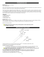
Page 10: ...until line is air free Close bleed screw Top off master cylinder as needed to prevent reintroducing air into the lines Repeat with remaining wheels DANGER Contamination with dirt water petroleum produ...

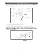
Page 11: ...or running gears equipped with used tires If either of the front tires look to be excessively worn or unevenly worn they should be rotated with a less worn rear tire if possible The front tires should...

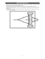
Page 12: ...ve onto the next step Measure both L2 locations Adjust both tie rods to assure both measurments are equal if necessary Finish with taking measurments for L3 and L4 L3 should be set 3 16 smaller than L...

Page 13: ...13...
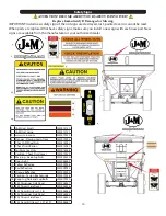
Page 14: ...228 14 Keep Lug Nuts and Lug Bolts JM0019220 15 455 Passenger Side Decal JM0036547 16 455 Drivers Side Decal JM0036546 17 455 Decal Kit Items 1 16 JM0036566 18 555 Passenger Side Decal JM0036543 19 55...

Page 15: ...AL LAWS MAKE SURE ALL FLASHER AND TURN INDICATOR BRAKE LIGHTS ARE WORKING PROPERLY BEFORE INCIDENTAL HIGHWAY TRAVEL CAUTION FASTEN BOX SECURELY TO WAGON GEAR KEEP AWAY FROM MOVING PARTS DO NOT CLIMB I...

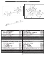
Page 16: ...r5 Z Hex Bolt 1434 HHMB JM0001507 20 5 16 18 Gr5 Z Star Washer Hex Nut JM0019361 Description Part No 21 015 Orifice Restrictor JM0027857 22 Master Cylinder with Spring Bracket MCA DR1 JM0019356 23 Mas...

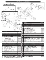
Page 17: ...18101 26 Cup Large Inner 15 Ton 382A JM0018100 27 Wheel Stud Lug 15 Ton WB 15 JM0019235 28 5 8 18 Flange Lugnut WN 15F JM0019246 29 G85 8 Oil Bath Outer Bearing Cup 16T JM0035896 30 G85 8 Oil Bath Sma...

Page 18: ...52 8 55 Series Fender JM0033393 9 3 8 16 x 1 Gr5 Z SF Hex Bolt JM0002092 10 Front Upper Left Fender Bracket 55 Series JM0033395 11 Front Upper Right Fender Bracket 55 Series JM0033435 12 Front Lower R...

Page 19: ...2 1 2 OD 1 8 Thick Zinc 12 W 212 JM0018982 8 Divider End Tab 555 JM0035861 9 Divider Sideboard 555 JM0035857 10 1 4 USS Flatwasher JM0003090 11 1 4 20 x 3 4 Gr5 Z Hex Bolt JM0001507 12 1 4 20 x 1 Gr5...

Page 20: ...4 1 4 20 Gr5 Z Centerlock Hex Nut 14HN JM0001505 5 3 4 Z Flat Washer 2 OD 34FW JM0010006 6 1 4 20 x 1 Gr5 Z Hex Bolt 141G5B JM0002095 7 Door Locking Rod DLR 1 JM0019097 8 Rubber End Cap REC 1 JM00168...

Page 21: ...Poly Tape attached to door JM0035980 6 1 2 Z Washer 2 1 4 OD 12214W JM0019081 7 1 4 Diameter Snap Ring Lynch Pin CTE LP JM0001870 8 Adjustable Chute Bracket for 60 Door 55 Series JM0035050 9 Dump Chut...

Page 22: ...Hex Bolt 381 FB JM0002092 17 3 8 16 x 1 1 2 Gr5 Z Hex Bolt JM0001659 18 1 4 20 Gr5 Z Centerlock Hex Nut 14HN JM0001505 19 Universal Joint SUJ 1 JM0001517 20 3 8 16 Gr5 Z Centerlock Hex Nut 38LN JM0001...

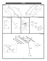
Page 23: ...23 Roll Tarp Bow Support Tarp Stand Off Crank Handle Holder Crank Handle U Joint Tarp Assembly Front Endcap Rear Endcap...

Page 24: ...tion Part No Red Light LED JM0034389 Amber Light LED JM0034392 Light Harness JM0027773 Light Enhancer JM0010566 Main Wiring Harness JM0027774 Flood Light JM0037154 A B C A B C A B C A B C LEFT 4 Prong...

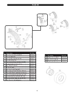
Page 25: ...Left Right assemblies available Items Included In Drum Clusters Backplate Assembly Front Brake Shoe Front Shoe Lever Rear Shoe Lever Wheel Cylinder Assembly Right or Left Screw and Lockwasher Adjusti...

Reviews: