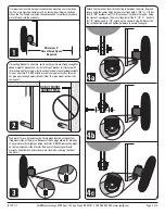
VRSBR14
(4) 5/16"
Nylock Nut
(2) 5/16” x 2-1/2”ID
U-Bolt
(4) 5/16"
Flat Washer
A
B
C
VRSBR143, VRSBR144, VRSBR14414
VRSBR12
VRSBR13
VRSBR2-HDG
VRSBR3-HDG
PROVIDING POWER TO FAN
ALL ELECTRICAL WORK
SHOULD BE COMPLETED
BY QUALIFIED PERSONNEL AND MEET
NATIONAL, REGIONAL AND LOCAL CODES.
MAINTENANCE INSTRUCTIONS
• Disconnect power before cleaning or maintaining your fan in order
to prevent serious injury or death.
• Service and repair of fan should only be completed by a qualified
technician.
• For maximum efficiency and fan life, keep the following free from
dirt and dust: blades, motor and guard.
• The totally enclosed air over motor has sealed ball bearings and
does not require additional oil.
Instructions for corded models
• Provide a grounded outlet that meets or exceeds the load capability
for your fan.
Wiring instructions for non corded models
• Wiring should only be performed by a trained electrician to prevent
injury or death.
• Install manual disconnect switch inside building adjacent to fan.
• Route wire to motor with drip loop and secure.
Drip loop will drain accumulated moisture away from the motor.
• Configure internal wires to match supply voltage and wire according
to motor nameplate. Test to verify correct rotation.
• Only permit power to unit when guard and motor’s cover plate is
properly installed to prevent injury.
Part #
Side Mount Brackets
VRSBR14
VRSBR143
VRSBR144
VRSBR14412
VRSB901
Ceiling Mount Brackets
VRSBR2-HDG
VRSBR3-HDG
Pole Mount Bracket
VRSBR12
VRSBR13
_____________________________________________
_____________________________________________
_____________________________________________
_____________________________________________
_____________________________________________
_____________________________________________
_____________________________________________
_____________________________________________
_____________________________________________
_____________________________________________
_____________________________________________
_____________________________________________
Fan Size
12”-36”
12”-36”
12”-36”
12”-36”
12”-36”
12”–24”
36”
12”-36”
12”-36”
Description
42” Extended Bracket, fits Square or Round Up Post
42” Extended Bracket, fits 3” Tube – Bolt On
42” Extended Bracket, fits 4” Tube – Bolt On
42” Extended Bracket, 4½” Tube – Bolt On
Wall Mount Bracket
6-Way Bracket
6-Way Bracket
Pole Bracket, fits 4”–4½” Tube
Pole Bracket, fits 3”–3½” Tube
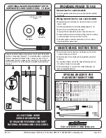
ADDITIONAL INCLUDED HARDWARE FOR THE
GREEN BREEZE AND EZ-BREEZE FANS - TO SCALE
Using the installation hardware shown above you can mount the included
bracket as shown below. Drawing “C” is acceptable without contradicting
the space requirement mentioned in step 1 on page 2 as long as there is
nothing behind the pipe to impede air flow. Use (2) 5/16” flat washers and
(2) 5/16” nylock nuts for each u-bolt used, assembled as shown below in
drawing A.
2a
OPTIONAL BRACKETS FOR
FLAG MOUNT BASKET FANS
IS123-11I
J&D Manufacturing • 6200 Hwy 12 • Eau Claire, WI 54701 • 1-800-998-2398 • www.jdmfg.com
Page 4 of 4
Visit our website at www.jdmfg.com


