
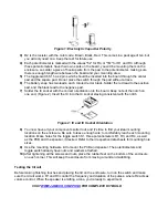

Figure 1: Electrolytic Capacitor Polarity
3)
R2 is the resistor with the color code: Brown, Black, Red. This comes in a package of ten, but
you will only need one. Keep the rest for future use.
4)
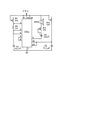
Each potentiometer is marked with the values "5k" for R4, or "1M" for R1 and R3. Although
these potentiometers have their own spots on the board, you will be mounting them on the
enclosure, so solder a piece of hookup wire from the pad to the potentiometer, making sure
there is enough length wire between the board and your mounting area.
5)
The toggle switch S1 has 2 pins which should be inserted into the board through the center
pad and the square pad. Do not place the switch through the pad without a trace.
6)
The battery snap has two leads, each colored red or black. Solder the red lead to the positive
pad, and the black lead to the negative pad.
7)
Solder the IC socket with the correct orientation onto the board. Keep note of the notch on
one end, (Figure 2). Insert the IC into the IC socket staying consistent with the notch.
Figure 2: IC and IC Socket Orientation
8)
You now have all your components sorted out, and it's time to find your ideal mounting
locations on the enclosure. Be sure to leave enough wire to comfortably reach each mounting
location. Make holes for the toggle switch S1, three potentiometers R1, R3, and R4, as well
as the PCB and the speaker, if desired. Refer to their respective datasheets for mounting hole
sizes.
9)
Use the mounting hardware kit to mount the PCB and speaker. The potentiometers and
toggle switch already have nuts and washers attached.
10)
After tightening all the screws and nuts, place the rubber feet on the bottom of the enclosure
on each corner. This will keep the enclosure from moving around and wobbling.
Testing the Circuit
Before making finishing touches and placing the lid on the enclosure, turn on the switch and make
sure the circuit works. R1 and R3 control the frequency and duration of the pulses, where R4 acts as
volume control. When the speaker is emitting a tone, you're ready to experiment.
FOR COMPLETE KIT BUILD
Summary of Contents for FORREST M. MIMS III: ATARI PUNK CONSOLE KIT
Page 3: ......


